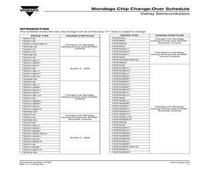
36LL1 TSOP2138LL1F Changed over Mondego marking working week 48 2008 December onwards TSOP2233 TSOP4133 TSOP4136 CHANGE-OVER PLAN www.vishay.com 1 Mondego Chip Change-Over Schedule Vishay Semiconductors DEVICE TYPE CHANGE-OVER PLAN TSOP2238YA1 TSOP2238ZC1 TSOP4838 TSOP4838AY1 TSOP4838DA1 TSOP4838LL1 TSOP4838QJ1 TSOP4838RF1 TSOP4838SB1 TSOP4838SI1 TSOP4838SJ1 TSOP4838SK1AM TSOP4838SO1 TSOP4838SP1 Changed over Mondego marking working week 44 2008 November onwards TSOP4838SS1BS12 TSOP4838SS1BS12Z TSOP4838SS1F TSOP4838ST1 TSOP4838UH1 TSOP4838VI1 TSOP4838YA1 TSOP4838UH1B TSOP4838LL1B TSOP4838YA1B TSOP58238 TSOP2240 TSOP2240RF1 TSOP4840 TSOP4840SB1 Quarter 2 - 2009 TSOP4840SI1 TSOP4840SJ1 TSOP58240 TSOP2256 TSOP2256IV1 TSOP2256SB1 TSO
 2 Pages, 16 KB, Original
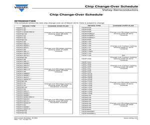
vishay.com 1 Chip Change-Over Schedule Vishay Semiconductors DEVICE TYPE Chip Change-Over Schedule CHANGE-OVER PLAN DEVICE TYPE TSOP6230 TSOP2238YA1 TSOP6233 TSOP2238ZC1 TSOP6256 TSOP6236 TSOP6237 Change-over Mondego marking working week 46 2009 - onwards TSOP4838 TSOP4838AY1 TSOP4838DA1 TSOP6238 TSOP4838LL1 TSOP6240 TSOP4838QJ1 TSOP2230 TSOP4830 TSOP58230 Changed-over Mondego marking working week 48 2008 December onwards TSOP4838RF1 TSOP4838SB1 TSOP4838SI1 TSOP2233 TSOP4838SJ1 TSOP2233LL1 TSOP4838SK1AM TSOP2233UH1 TSOP2233VI1 TSOP4833 Change-over Mondego marking working week 03 2009 - January onwards TSOP4838SO1 TSOP4838SP1 TSOP4838SS1BS12Z TSOP58233 TSOP4838SS1F TSOP2236 TSOP4838ST1 TSOP2236AY1 TSOP4838UH1 TSOP2236KU1 TSOP4838VI1 TSOP2236LL1 TSOP4838YA1 TSOP2236QJ1 TSOP48
 2 Pages, 19 KB, Original
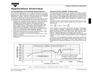
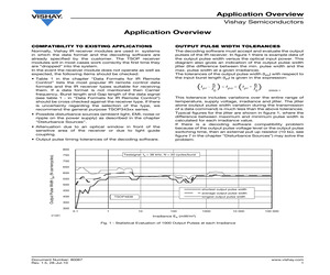
 pulse switching time then an external pull up resistor (10 k, see Figure 9 - in "Disturbance Sources Section") may solve the problem. Output Pulse Width [s] 800 Testsignal: f0 =38kHz, N=20cycles/burst 750 700 650 600 550 500 450 400 shortest output pulse TSOP4838 longest output pulse average output pulse width 350 300 0.1 1 10 100 1000 10000 100000 Irradiance [mW/m] 17066 Figure 1. Statistical Evaluation of 1000 Output Pulses at each Irradiance Document Number: 80067 Rev. A2, 05-Aug-03 www.vishay.com 1 VISHAY Vishay Semiconductors Example of Application Circuit for Remote Control of a circuit without any other micro controller that can include the decoding software for the IR signal, a possibility could be the circuit in Figure 2 using the RC5 Code and ICs from Philips. If a new system is set up then an already existing micro controller may be used for decoding the remote control signal coming from the IR receiver. In the case +3V 220 F +5V 2.2 100 TSAL6400 Data 10 F Address Toggle Keys TSOP4836
 6 Pages, 92 KB, Original
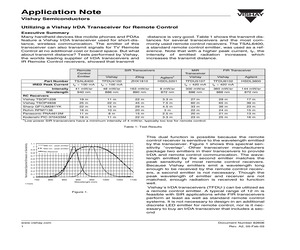
 radiation increases which increases the transmit distance. SIR Transceivers MIR Transceiver Vishay Zilog Agilent1 ZHX1810 HSDL3201 TSAL6400 TFDU4100 IF = 100 mA IF = 100 mA 41 mW/sr 48 mW/sr 163 mW/sr 940 nm 886 nm 890 nm Vishay TSOP1238 19 m 11 m Vishay TSOP4838 25 m 22 m Sharp GP1UM281YK 22 m Rohm RPM7138 Vishay FIR Transceiver Vishay Agilent HSDL3600 TFDU5107 TFDU6102 IF = 420 mA IF = 420 mA 8 mW/sr 300 mW/sr 360 mW/sr 144 mW/sr 872 nm 886 nm 886 nm 872 nm 22 m 3.3 m 27 m 29 m 17 m 45 m 7.5 m 60 m 65 m 39 m 15 m 29 m 4.5 m 33 m 36 m 23 m 16 m 10 m 20 m 3m 22 m 24 m 15 m Panasonic PNA4612M 11 m 8m 15 m 2.5 m 20 m 21 m 13 m Kodenshi PIC-37043SM 18 m 11 m 22 m 3.3 m 23 m 25 m 16 m Part Number IRED Peak Current Intensity Wavelength RC Receivers 1 Low-power SIR transceivers have a minimum intensity of 4 mW/sr, typically too low for remote control. Normalized Spectral Emission or Sensitivity Table 1: Test Results 1.1 1 0.9 0.8 "886 nm - peak emitter" "950 nm - peak emitter" RC-Receiver 0.7 0.6 0.5
 4 Pages, 300 KB, Original
W SCREW BACK COVER ASS'Y WIRE HOLDER KENSINGTON LOCK PC PLATE ON TOP REAR COVER SPONGE SCREW SCREW BEZEL ASS'Y ID2 KEYPAD COVER ID2 FUNC KEY ID2 COVER POWER KEY ID2 LENS REMOTE LENS SPONGE 8OHM SPEAKER 8OHM SPEAKER SCREW SCREW IR BOARD FOR ROHS WAFER PH-4 TSOP4838 HARNESS 95MM IR BOARD FOR SMT PMBS3906/PHILIPS-SMT CHIP 100OHM 1/16W CHIP 10KOHM 1/16W RST CHIPR 1 KOHM +-5% 1/4W RST CHIPR 1.5 KOHM +-5% 1/4W CHIP 100PF 50V X7R CHIP 0.1UF 50V X7R CHIP 0.1UF 50V X7R CHIP 0.1UF 50V X7R CHIP 4.7UF 10V X5R CHIP BEAD 600OHM 0603 TB1608 CHIP BEAD 600OHM 0603 TB1608 CHIP BEAD 600OHM 0603 TB1608 KAA-3528CGKSYKC-01-AOC SMA IR BOARD KEY BOARD WAFER 4P RIGHT ANGLE TACT SWITCH TSPB-2 -NP TACT SWITCH TSPB-2 -NP TACT SWITCH TSPB-2 -NP TACT SWITCH TSPB-2 -NP TACT SWITCH TSPB-2 -NP TACT SWITCH TSPB-2 -NP TACT SWITCH TSPB-2 -NP LED GP31032C-R003-ZR-35 67 32'' LCD TV Q2 R47 R3 R11 R4 R1 R7 R5 R2 R6 R9 R12 C4 C44 C45 C5 L10 L1 L2 CN951 CN952 IC922 IC924 IC925 IC942 NR902 NR901 R950 R921 R905 R945 C901 C905 C926 C922 AOC
 99 Pages, 9609 KB, Original
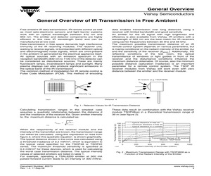
nimum possible distance (saturation irradiance) is an important parameter for a remote control system. The TSOP IR receiver modules from Vishay will work even with zero distance between the emitter and the receiver module. IR transmitter IR receiver (e.g. TSOP4838) Irradiance E e Intensity I e Distance d 17077 Fig. 1 - Relevant Values for IR Transmission Distance dm ax. = 20169 Ie -----------E e min. When the responsivity of the receiver module and the intensity of the transmitter are known, the transmission range can either be calculated using this expression or read from figure 2, where this quadratic equation is shown graphically. The typical distance shown in the curve was calculated using a threshold irradiance of 0.2 mW/m2, which is equivalent to the typical value specified for the TSOP48 or TSOP22 series. The maximum threshold sensitivity is specified at 0.4 mW/m2 for these devices, which is used for calculating the worst case transmission distance. The typical intensity values of selected
 2 Pages, 34 KB, Original
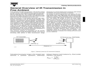
influence the choice of distance. Of course, also the minimum possible distance (high irradiance) is an important value for a remote control system. The TSOP IR receiver modules from Vishay will work even at zero distance. IR Transmitter IR Receiver (e.g. TSOP4838) Irradiance E e Intensity I e Distance d 17077 Figure 1. Relevant Values for IR Transmission Distance Calculating transmission ranges in the simplest case assumes a quadratic expression relationship between distance d and irradiance Ee. Given emitter intensity Ie, the result is d max = Document Number: 80073 Rev. A2, 05-Aug-03 Ie ------------E emin www.vishay.com 1 VISHAY Vishay Semiconductors Transmission Range [m] With known responsivity of the receiver module and known intensity of the transmitter, the transmission range can be calculated with this expression or read from Figure 2 where this quadratic equation for distance is implemented. As a typical threshold of the receiver sensitivity for safe operation, a value of 0.2 mW/m2 is t
 3 Pages, 39 KB, Original
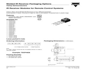
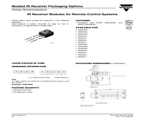
2 3 16672 Loose packed in tube Packaging Dimensions in millimeters Ordering Information T S O P d d 2 or 3 digit product series d d d 2 digit frequency Note: d = "digit", please consult the list of available devices to create a valid part number. Example: TSOP4838 Packing Quantity * 90 pieces per tube * 24 tubes per carton Drawing-No.: 9.700-5185.0-4 Rev. 13; Date: 20.11.03 20273-1 www.vishay.com 44 Document Number 81620 Rev. 1.0, 15-Dec-06 Molded IR Receiver Packaging Options Vishay Semiconductors Tape and Reel/Ammopack Up to 3 consecutive components may be missing if the gap is followed by at least 6 components. A maximum of 0.5 % of the components per reel quantity may be missing. At least 5 empty positions are present at the start and the end of the tape to enable insertion. Tensile strength of the tape: > 15 N Pulling force in the plane of the tape, at right angles to the reel: > 5 N Ordering Information T S O P d 2 or 3 digit product series d d d d 2 digit frequency S S 1 SS1 for T&R, Bulk
 3 Pages, 78 KB, Original
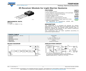
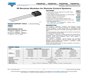
FOR LONG BURST REMOTE CONTROLS (AGC2) AGC Carrier frequency RECOMMENDED FOR LONG BURST CODES (AGC4) 30 kHz TSOP4830 TSOP2230 TSOP4430 33 kHz TSOP4833 TSOP2233 TSOP4433 TSOP2430 TSOP2433 36 kHz TSOP4836 TSOP2236 TSOP4436 (1)(2)(3) TSOP2436 (1)(2)(3) 38 kHz TSOP4838 TSOP2238 TSOP4438 (4)(5)(6) TSOP2438 (4)(5)(6) 40 kHz TSOP4840 TSOP2240 TSOP4440 TSOP2440 56 kHz TSOP4856 TSOP2256 TSOP4456 (6)(7) TSOP2456 (6)(7) Package Mold Pinning 1 = OUT, 2 = GND, 3 = VS 1 = OUT, 2 = VS, 3 = GND 1 = OUT, 2 = GND, 3 = VS 1 = OUT, 2 = VS, 3 = GND Dimensions (mm) 6.0 W x 6.95 H x 5.6 D Mounting Leaded Application Best choice for Rev. 1.8, 26-Sep-2018 Remote control (1) RC-5 (2) RC-6 (3) Panasonic 1 (4) NEC (5) Sharp (6) r-step (7) Thomson RCA Document Number: 82459 THIS DOCUMENT IS SUBJECT TO CHANGE WITHOUT NOTICE. THE PRODUCTS DESCRIBED HEREIN AND THIS DOCUMENT ARE SUBJECT TO SPECIFIC DISCLAIMERS, SET FORTH AT www.vishay.com/doc?91000 TSOP22.., TSOP24.., TSOP48.., TSOP44.. www.vishay.com Vishay Semiconductors BLOCK
 8 Pages, 183 KB, Original
d 2 or 3 digit product series O = for IR receiver applications M = for repeater/learning applications S = for sensor applications d d d 2 digit frequency Note * d = "digit", please consult the list of available devices create a valid part number. Example: TSOP4838 PACKAGING QUANTITY * 90 pieces per tube * 24 tubes per carton Drawing-No.: 9.700-5185.0-4 Rev. 13; Date: 20.11.03 20273-1 Rev. 1.4, 19-Apr-12 1 Document Number: 81620 THIS DOCUMENT IS SUBJECT TO CHANGE WITHOUT NOTICE. THE PRODUCTS DESCRIBED HEREIN AND THIS DOCUMENT ARE SUBJECT TO SPECIFIC DISCLAIMERS, SET FORTH AT www.vishay.com/doc?91000 Molded IR Receiver Packaging Options www.vishay.com Vishay Semiconductors TAPE AND REEL/AMMOPACK Up to 3 consecutive components may be missing if the gap is followed by at least 6 components. A maximum of 0.5 % of the components per reel quantity may be missing. At least 5 empty positions are present at the start and the end of the tape to enable insertion. Tensile strength of the tape: > 15 N Pulling
 9 Pages, 245 KB, Original
21.. TSOP24... TSOP22... TSOP21... PACKAGING DIMENSIONS in millimeters ORDERING INFORMATION T S O P d d 2 or 3 digit product series d d d 2 digit frequency Note d = "digit", please consult the list of available devices create a valid part number. Example: TSOP4838 PACKING QUANTITY * 90 pieces per tube * 24 tubes per carton Drawing-No.: 9.700-5185.0-4 Rev. 13; Date: 20.11.03 20273-1 www.vishay.com 52 Document Number: 81620 Rev. 1.2, 17-Sep-08 Molded IR Receiver Packaging Options IR Receiver Modules for Remote Control Systems Vishay Semiconductors TAPE AND REEL/AMMOPACK Up to 3 consecutive components may be missing if the gap is followed by at least 6 components. A maximum of 0.5 % of the components per reel quantity may be missing. At least 5 empty positions are present at the start and the end of the tape to enable insertion. Tensile strength of the tape: > 15 N Pulling force in the plane of the tape, at right angles to the reel: > 5 N O 355 1 O 30 Label 20 0.5 12.7 1 2 0.9 max. 0.3 0.2 O4 0.2 Kr
 3 Pages, 1690 KB, Original
CHIP 2SC3875S(ALY) BK KEC CHIP 2SC3875S(ALY) BK KEC CHIP 2SC3875S(ALY) BK KEC 1K OHM 1 / 10 W 2012 5.00% D 100 1/10W 5 D.R/TP 560 1/10W 5 D.R/TP 100 1/10W 5 D.R/TP 1K OHM 1 / 10 W 2012 5.00% D 100 1/10W 5 D.R/TP 4.3K 1/10W 5 TA SAM5670(DL-2LRG) BK Y-GREEN TSOP4838SO1 VISHAY 38.0KHZ H - 34 - REPLACEMENT PARTS LIST(RT-20LZ50) For Capacitor & Resistors, the charactors at 2nd and 3rd digit in the P/No. means as follows; *S *AL LOC. NO. PART NO. CC, CX, CK, CN, CH : Ceramic CQ : Polyestor CE : Electrolytic CF : Fixed Film DATE: 2004. 11. 18. DESCRIPTION / SPECIFICATION *S *AL LOC. NO. MAIN BOARD CAPACITOR C1008 C1101 C1104 C1107 C1140 C1152 C123 C124 C131 C132 C133 C134 C1150 C1151 C127 C128 C135 C136 C15 C16 C19 C4 C41 C44 C49 C6 C803 C804 C808 C810 C812 C851 C855 C858 C861 C863 C865 C866 C867 C869 C871 C874 C875 C877 C909 C910 C917 C920 C925 C926 C927 C928 0CE227CF638 0CE227BH638 0CE227BH638 0CE477BH618 0CE227BH638 0CE107BK638 0CE477BH618 0CE477BH618 0CE477BH618 0CE477BH618 0CE477BH618 0CE477BH618 0
 42 Pages, 3028 KB, Original
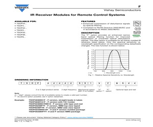
ency Mechanical option "V" "F" (SS1 if no holder) option (1) option B S d d Optional tape and reel Note d = "digit", please consult the list of available series to create a valid part number. (1) As second option possible; see V option datasheet. Example: TSOP4838SS1F - F version, straight leads in tubes TSOP4838YA1F - F version with YA1 holder TSOP2238SS1FBS12 - F version with tape and reel TSOP35238FTT - F version, SMD top view taped TSOP6236FTR - F version, SMD side view taped TSOP32338SS1VF - V and F version molded package TSOP35338VFTT- V and F version SMD package ** Please see document "Vishay Material Category Policy": www.vishay.com/doc?99902 Document Number: 81590 Rev. 1.4, 11-Feb-11 www.vishay.com 1
 1 Pages, 33 KB, Original
FOR LONG BURST REMOTE CONTROLS (AGC2) AGC Carrier frequency RECOMMENDED FOR LONG BURST CODES (AGC4) 30 kHz TSOP4830 TSOP2230 TSOP4430 33 kHz TSOP4833 TSOP2233 TSOP4433 TSOP2430 TSOP2433 36 kHz TSOP4836 TSOP2236 TSOP4436 (1)(2)(3) TSOP2436 (1)(2)(3) 38 kHz TSOP4838 TSOP2238 TSOP4438 (4)(5)(6) TSOP2438 (4)(5)(6) 40 kHz TSOP4840 TSOP2240 TSOP4440 TSOP2440 56 kHz TSOP4856 TSOP2256 TSOP4456 (6)(7) TSOP2456 (6)(7) Package Mold Pinning 1 = OUT, 2 = GND, 3 = VS 1 = OUT, 2 = VS, 3 = GND 1 = OUT, 2 = GND, 3 = VS 1 = OUT, 2 = VS, 3 = GND Dimensions (mm) 6.0 W x 6.95 H x 5.6 D Mounting Leaded Application Best choice for Rev. 1.8, 26-Sep-2018 Remote control (1) RC-5 (2) RC-6 (3) Panasonic 1 (4) NEC (5) Sharp (6) r-step (7) Thomson RCA Document Number: 82459 THIS DOCUMENT IS SUBJECT TO CHANGE WITHOUT NOTICE. THE PRODUCTS DESCRIBED HEREIN AND THIS DOCUMENT ARE SUBJECT TO SPECIFIC DISCLAIMERS, SET FORTH AT www.vishay.com/doc?91000 TSOP22.., TSOP24.., TSOP48.., TSOP44.. www.vishay.com Vishay Semiconductors BLOCK
 8 Pages, 180 KB, Original
apter "Disturbance Sources") may solve the problem. Output Pulse Width tpo (N carriercycles) 800 Testsignal: f0 = 38 kHz, N = 20 cycles/burst 750 700 650 600 550 500 shortest output pulse width 450 400 average output pulse width longest output pulse width TSOP4838 350 300 0.1 21491 1 10 100 1000 10 000 100 000 Irradiance Ee (mW/m) Fig. 1 - Statistical Evaluation of 1000 Output Pulses at each Irradiance Document Number: 80067 Rev. 1.5, 28-Jul-10 www.vishay.com 1 Application Overview Application Overview Vishay Semiconductors APPLICATION CIRCUIT FOR OPERATION IN HARSH ENVIRONMENTS The Vishay IR receivers include an efficient protection circuitry against electrostatic discharge (ESD) or electrical overstress (EOS), which is sufficient for normal handling and assembly procedures according the common industry standards. In case of serious over-voltage-transients it might be useful to add components for a further improvement of the protection. If the robustness of the IR receiver for an air discharge E
 5 Pages, 69 KB, Original


