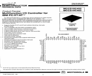
S16C452/D ~TECHNICAL DATA MCCS16C452 Product Preview MCCS16C462 Multifunction I/O Controller for IBM PC/XT/AT The MCCS16C452/462 is a multifunction device designed for mother boards or add-in cards, and is compatible with IBM PC/XT/AT systems. The MCCS16C452/462 has two NS16450 compatible asynchronous communications elements to provide serial ports, and a bidirectional parallel port interface that supports a Centronics type printer and allows the parallel port to receive data from external devices. FN PACKAGE e Supports flexible PC/XT and AT port address decoding, interrupts, PLASTIC and bus cycles CASE 779 100% compatible with NS16450 and NS8250 UART ; . : Ordering Information e Two full-duplex asynchronous receivers/transmitters MCCS16C452FN e Programmable serial interface character length MCCS16C462FN e Programmable baud rate for each receiver and transmitter e Full modem control functions e Double buffering in character mode False start-bit
 28 Pages, 2365 KB, Scan
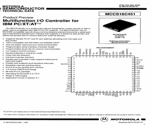
S16C451/D 1SEMICONDUCTOR se ~ TECHNICAL DATA MCCS16C451 Product Preview Multifunction I/O Controller for IBM PC/XT/AT The MCCS16C451 is a multifunction device designed for mother boards or add-in cards, and is compatible with IBM PC/XT/AT systems. The MCCS16C451 has an NS16450 compatible asynchronous communications element to provide a serial port, and a bidirectional parallel port interface that supports a Centronics type printer and FN PACKAGE allows the parallel port to receive data from external devices. PLASTIC CASE 779 e Supports flexible PC/XT and AT port address decoding and interrupts and bus cycles Ordering Information 100% compatible with NS16450 and NS8250 UART MCCS16C451FN e One full-duplex asynchronous receiver/transmitter e Programmable serial interface character length PIN ASSIGNMENT e Programmable baud rate for receiver and transmitter a 998 a a . > > > > = e Full modem control functions fea xc a yw 5 & Double b ng inch Aon wm @
 27 Pages, 2063 KB, Scan
t characteristics, a detailed function and timing section, a discussion of software compatibility issues and the AC timing parameters. 1.0 Part Summary The seven versions currently produced are designated INS8250, INS8250-B, INS8250A, NS16450, INS82C50A, NS16C450, and NS16550AF. These devices are grouped below by process type. C1995 National Semiconductor Corporation TL/C/9320 wants this part should order the NS16550AF. Section 5.0 describes the differences between the NS16550 and the NS16550AF in detail. CMOS DEVICES 1. INS82C50A: This is a CMOS version of the INS8250A. It functions identically and for most AC parameters has the same timing specification as the INS8250A (see Section 4.0). It draws approximately 1/10 (10 mA) of the maximum operating current of the INS8250A. 2. NS16C450: This is a CMOS version of the NS16450. It functions identically and for most AC parameters has the same timing specification as the NS16450 (see Section 4.0). It draws approximately 1/12 (10 mA) of th
 8 Pages, 76 KB, Original
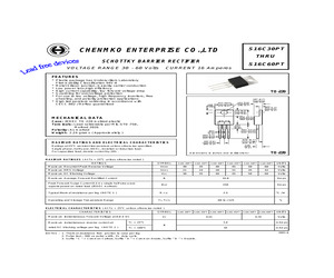
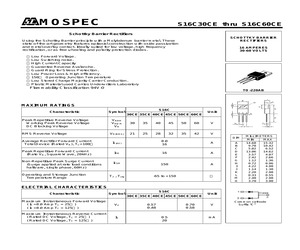
lf wave, 60 HZ, resistive or inductive load. For capacitive load, derate current by 20%. .020 (0.5) .126 (3.2) TO-220 Dimensions in inches and (millimeters) MAXIMUM RATINGES ( At TA = 25oC unless otherwise noted ) RATINGS SYMBOL S16C30PT S16C35PT S16C40PT S16C45PT S16C50PT S16C60PT UNITS Maximum Recurrent Peak Reverse Voltage VRRM 30 35 40 45 50 60 Volts Maximum RMS Voltage VRMS 21 24 28 31 35 42 Volts Maximum DC Blocking Voltage VDC 30 35 40 45 50 60 Maximum Average Forward Rectified Current Peak Forward Surge Current 8.3 ms single half sine-wave superimposed on rated load (JEDEC method) 16.0 Amps IFSM 150 Amps R Typical thermal resistance per leg ( NOTE 1 ) Operating and Storage Temperature Range Volts IO o 2.5 JC TJ, TSTG C/W o -60 to +125 C ELECTRICAL CHARACTERISTICS ( At TA = 25oC unless otherwise noted ) CHARACTERISTICS SYMBOL Maximum Instantaneous Forward Voltage at 8.0 A DC Maximum instantaneous reverse current at S16C30PT S16C35PT S16C40PT S16C45PT S16C50PT S16C60PT VF TC =
 2 Pages, 58 KB, Original
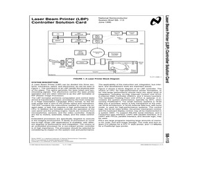
ized instructions for printer operations. Component Count Reduce component count through efficient bus architecture, integration, and code density. KEY COMPONENTS NS32CG16, NS32CG160, NS32FX16, NS32GX32 or NS32GX320, NS32081, NS32181 or NS32381 NS32CG821 NS16C451/NS16C551 EPROM DRAM EEPROM CPU Function FPU Function DRAM Controller Designed to Interface with Series 32000 Embedded Processor UART with Parallel Interface, (FIFOs, and Decode Logic) Program and Font Storage Working Space and Data Buffers Setup Storage BILL OF MATERIAL OF MAJOR COMPONENTS 15 PPM LBP CONTROLLER Function Description NSC Part Other Mfg Qty CPU Embedded Processor NS32GX320 1 FPU Floating-Point Unit NS32381 1 Interface Serial and Parallel Interface NS16C451 1 EPROM 1 Mbyte NMC27C010 8 DRAM 4 Mbyte EEPROM Memory Control 256 Byte DRAM Controller NMC93CS56 NS32CG821 1 1 Interface (Note 1) 1 Memory Logic System ASIC Note 1: The system ASIC may be designed using National's ASIC capabilities. 3 Laser Beam Printer (LBP
 4 Pages, 65 KB, Original
nstantaneous Reverse Current ( Rated DC Voltage, TC = 25) ( Rated DC Voltage, TC = 125) IR 0.57 0.48 0.70 0.58 0.5 20 V mA Common cathode Suffix "C" S16C30CE Thru S16C60CE NSTANTANEOUS FORWARD CURRENT (Amp.) FIG-2 TYPICAL FORWARD CHARACTERISITICS S16C30CE-S16C45CE S16C50CE-S16C60CE CASE TEMPERATURE () FORWARD VOLTAGE (Volts) FIG-3 TYPICAL REVERSE CHARACTERISTICS FIG-4 TYPICAL JUNCTION CAPACITANCE S16C30CE-S16C45CE S16C50CE-S16C60CE PERCENT OF RATED REVERSE VOLTAGE () PEAK FORWARD SURGE CURRENT (Amp.) FIG-5 PEAK FORWARD SURGE CURRENT NUMBER OF CYCLES AT 60 Hz JUNCTION CAPACITANCE (PF) INSTANTANEOUS REVERSE CURRENT (mA.) AVERAGE FORWARD RECTIFIED CURRENT (Amp.) FIG-1 FORWARD CURRENT DERATING CURVE S16C30CE-S16C45CE S16C50CE-S16C60CE REVERSE VOLTAGE (Volts)
 2 Pages, 82 KB, Original
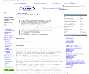
/1 Tx/RxFIFOCtrs No Tx/RxFIFOINT Trig No/No AutoRTS/CTS No IrDaSup No 5VTolInputs Yes Sup V 2.97-5.5 Pkgs PLCC-68 How to Buy Design Technical Documentation Technical FAQs Pin to pin and functional compatible to TL16C452 Software compatible with ST16C450, NS16C450 1.5 Mbps transmit/receive operation (24MHz) Independent transmit and receive control Modem and printer status registers UART port and printer port Bi-directional Printer port direction set by single control bit or 8 bit pattern (AA/55) Modem control signals (-CTS, -RTS, -DSR, -DTR, -RI, -CD) Programmable character lengths (5, 6, 7, 8) Even, odd, or no parity bit generation and detection Internal loop-back diagnostics TTL compatible inputs, outputs Low Power Pb-Free, RoHS Compliant Versions Offered Product Finder Product Tree Datasheets Applications Technical Support Parallel Printer Port Packaging Evaluation Boards Cross References Product Change Notifications Obsolescence Interface Brochure IBIS Models BSDL ICI UART Finder Documents Des
 32 Pages, 237 KB, Original
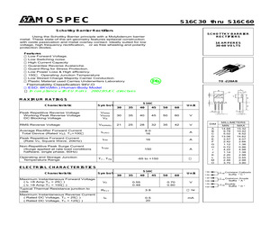
2 1.36 0.72 0.96 4.22 4.98 1.14 1.38 2.20 2.98 0.33 0.55 2.48 2.98 3.70 3.90 S16C30 Thru S16C60 FIG-2 TYPICAL FORWARD CHARACTERISITICS NSTANTANEOUS FORWARD CURRENT (Amp.) AVERAGE FORWARD RECTIFIED CURRENT (Amp.) FIG-1 FORWARD CURRENT DERATING CURVE S16C30-S16C45 S16C50-S16C60 CASE TEMPERATURE () FORWARD VOLTAGE (Volts) FIG-3 TYPICAL REVERSE CHARACTERISTICS FIG-4 TYPICAL JUNCTION CAPACITANCE o Tj=75 c o Tj=25 c PERCENT OF RATED REVERSE VOLTAGE () PEAK FORWARD SURGE CURRENT (Amp.) FIG-5 PEAK FORWARD SURGE CURRENT NUMBER OF CYCLES AT 60 Hz JUNCTION CAPACITANCE (PF) INSTANTANEOUS REVERSE CURRENT (mA.) o Tj=100 c S16C30-S16C45 S16C50-S16C60 REVERSE VOLTAGE (Volts)
 2 Pages, 76 KB, Original
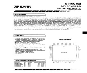
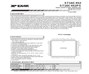
the printer port data direction to become compatible PS/2 operating system. The 452/452PS is fabricated in an advanced CMOS process with low power consumption. FEATURES ] Pin to pin and functional compatible to TL16C452 Software compatible with ST16C450, NS16C450 PLCC Package 1.5 Mbps transmit/receive operation (24MHz) independent transmit and receive control * Modem and printer status registers UART port and printer port Bi-directional Printer port direction set by single control bit or 8 bit 68. ACK 67, PE 83! ERHOR 66' BUSY i 68) SLCT 8 VOC Paz, Axe pattern {AA/55) 8 ie ~ se, INTB + DIRE. 1h 4 7595 INTE * Modem control signals (-CTS, -RTS, -DSR, -DTR, oe Seam -Ri, -CD) CTSB 1d | PEEL ner Programmable character lengths (5, 6, 7, 8) os | Lie utoro Even, odd, or no parity bit generation and detection ms pe ee . : 02 16 i p54, GND internal loopback diagnostics os | | Tee on TTL compatible inputs, outputs onl | St eedeee Res | Tse eo: Low Power ag [78] | bats oo 6 i 20 | | [Ba P28 Dy 24 j foes Poe
 28 Pages, 1359 KB, Scan
ts may be used as a pointer to the appropriate interrupt service routine. 1=no interrupt pending. ISR BIT 1-3: Logical combination of these bits, provides the highest priority interrupt pending. ISR BIT 4-7: These bits are not used and are set to zero in MS16C450 mode. BIT 6-7:are set to "1" in MS16C554 mode. FIFO CONTROL REGISTER (FCR) This register is used to enable the FIFOs, clear the FIFOs, set the receiver FIFO trigger level, and select the type of DMA signaling. FCR BIT-0: 0=Diosable the transmit and receive FIFO. 1=Enable the transmit and receive FIFO. This is bit should be enabled before setting the FIFO trigger levels. FCR BIT-1: 0=No change. 1=Clears the contents of receive FIFO and resets its counter logic to 0 ( the receive shift register is not cleared or altered). This bit will return to zero after clearing the FIFOs. FCR BIT-2: 0=No change. 1=Clears the contents of the transmit FIFO and resets its counter logic to 0 (the transmit shift register is not cleared or altered). This bit
 20 Pages, 499 KB, Original
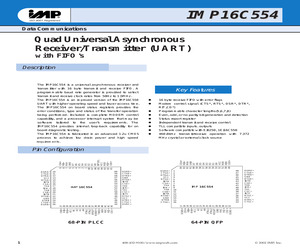
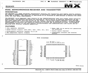
fer control capability, and a processor interrupt system t ynchronous receiver and transmitter with modern control signals. generator is provided to select transmit and receive clock rates s fabricated in an advanced 2u CMOS process to achieve low drain /NS16C450 UART with higher speed operating parallel to serial/serial to parallel conversion on the the MODEM. The can interface easily to the most popular microprocessors detected with internal loopback capability. FEATURES * DUAL INS8250A, NS16C450 | | requirements to minimize the computing required to han | operations being performed, hat may be software tailored to the user's dle the communications link. on board status registers will provide Complete MODEM The MX16C453 and communications link faults can be * Even, odd, or no parity bit generation and detection * Modem control signals (CTS-,RTS-, DSR-, DTR-, RI-, CD-) * Programmable character lengths (5,6,7,8) * TTL compatible inputs, outputs * Status report register * Independent
 19 Pages, 1366 KB, Scan
6 37 38 39 40 41 42 43 -CDA -RIA -DSRA -CSA A2 A1 A0 -IOW -IOR -CSP -RESET VCC RXA N.C. INTSEL ST16C452CJ68 ST16C452CJ68PS GND ORDERING INFORMATION PLCC Package -CTSA * Pin to pin and functional compatible to TL16C452 * Software compatible with ST16C450, NS16C450 * 1.5 Mbps transmit/receive operation (24MHz) * Independent transmit and receive control * Modem and printer status registers * UART port and printer port Bi-directional * Printer port direction set by single control bit or 8 bit pattern (AA/55) * Modem control signals (-CTS, -RTS, -DSR, -DTR, -RI, -CD) * Programmable character lengths (5, 6, 7, 8) * Even, odd, or no parity bit generation and detection * Internal loop-back diagnostics * TTL compatible inputs, outputs * Low Power Operating temperature 0 C to + 70 C 0 C to + 70 C -40 C to + 85 C -40 C to + 85 C Rev. 3.10 EXAR Corporation, 48720 Kato Road, Fremont, CA 94538 * (510) 668-7000 * FAX (510) 668-7017 ST16C452/452PS Transmit Holding Registers Transmit Shift Register TX A,B Receive
 31 Pages, 288 KB, Original
X AY1-1320 ERA-1 I1-205-5 IR2E02 IR2C19 LH0002CN OP02EZ REF-02CP VN02 IR3C02* R03-2513 ADXL05JH N5C060-45 OP05EP OP05 MAR-6 OP06GJ OP07 DAC08 MAR-8 8T26 8T28 8T95 8T96 8T97 DAC10GX LM10CH IMSC011-S20E SMP11G4 11C90DC LM12CZK 14C88 14C89 STK-0015 PIC16C74 MS16C450CP-40 MS16C451CQ-68 GM16C550 OP16GZ PA0016 PAL16L8A PAL16R8A GAL16V8-25 OP17GZ PEEL18CV8J TBP18SA030J LP20D5B3TS PAL20L8A-2CN PALCE20V8H-15 VB020 PEEL22L10-25 22V10Z-25 GAL22V10-25 26LS31 26C32ACN 26LS32 27L4C* OP27 TS27L2C LH0033CG Quad bus Transceiver Quad bus Transceiver Hex Three State Hex Inverter Hex Buffer 10 bit D/A Omvandlare Op.Amp med spann.ref. Transputer Link Adaptor,10 or 20 Mb/s Sample and Hold Counter Divide by 10/11 Prescaler,650MHz 80W Op.Amp Quad line Driver Quad line Reciver AF Power Amp 10W 32V EE prom 4096x14 UART med Baudrate-generator UART m.Baudr.-gen.&Centr.Interface UART med Baudrate-generator Precision J-FET Input Op-Amp PIONEER One-Time Prog.-Combinatorial Output One-Time Prog.-Registered Outputs
 120 Pages, 656 KB, Original
 compatible asynchronous serial ports (COM1 and COM2) provide a means to communicate with external serial devices such as printers, modems, etc. Each is independently configured as a standard PC COM port that is compatible with the National Semiconductor NS16C450. COM1 appears in the I/O space at 3F8h - 3FFh and uses IRQ4. COM2 is located at 2F8h - 2FFh and uses IRQ3. By changing an internal configuration register in the 386EX, the serial clock to the COM ports can be switched to 16.50 MHz. This feature allows baud rates higher than 115 Kbaud, as well as non-standard lower baud rates (such as 24 Kbaud). See Appendix G for further information. The COM ports may also be configured to use a DMA channel, which is handy when very high baud rates are being used. When enabled, a DMA request is issued any time a serial port's receive buffer is full or its transmit buffer is empty. This allows higher speed operation with much lower CPU overhead. See the Intel 386EX User's Manual for further details. 5.1 S
 33 Pages, 282 KB, Original
. INTSEL ST16C452CJ68 ST16C452CJ68PS -CTSA Added features in devices with top mark date code of "F2 YYWW" and newer: * 5V Tolerant Inputs * Pin to pin and functional compatible to TL16C452 * 2.97 to 5.5 volt operation * Software compatible with ST16C450, NS16C450 * 1.5 Mbps transmit/receive operation (24MHz) * Independent transmit and receive control * Modem and printer status registers * UART port and printer port Bi-directional * Printer port direction set by single control bit or 8 bit pattern (AA/55) * Modem control signals (-CTS, -RTS, -DSR, -DTR, -RI, -CD) * Programmable character lengths (5, 6, 7, 8) * Even, odd, or no parity bit generation and detection * Internal loop-back diagnostics * TTL compatible inputs, outputs * Low Power 9 FEATURES ORDERING INFORMATION Part number Package ST16C452CJ68 ST16C452CJ68PS ST16C452IJ68 ST16C452IJ68PS 68-Lead 68-Lead 68-Lead 68-Lead Operating temperature PLCC PLCC PLCC PLCC 0 C to + 70 C 0 C to + 70 C -40 C to + 85 C -40 C to + 85 C Device Status Active
 30 Pages, 152 KB, Original


