tch must be changed to the PIM position (upward). The respective DIGIO signal mappings on the P1 and P2 headers are detailed in Table 2-22. Note 1: In the default state, headers P1 and P2 are not assembled. These headers can each be populated with a Molex 87758-4616. 2: The user must ensure that the EEPROM is configured in DIGIO mode. TABLE 2-22: DIGIO MODE P1 & P2 HEADER SIGNALS HBI Indexed HBI Multiplexed DIGIO P1/P2 Pin RD/RD_WR RD/RD_WR DIGIO15 P1.8 WR/ENB WR/ENB DIGIO14 P1.10 CS CS DIGIO13 P1.26 A4 - DIGIO12 P1.41 A3 - DIGIO11 P1.44 A2 ALEHI DIGIO10 P2.21 A1 ALELO OE_EXT P1.7 A0/D15 AD15 DIGIO9 P1.15 D14 AD14 DIGIO8 P1.16 D13 AD13 DIGIO7 P1.11 D12 AD12 DIGIO6 P1.12 D11 AD11 DIGIO5 P1.17 D10 AD10 DIGIO4 P1.14 D9 AD9 LATCH_IN P1.13 D8 AD8 DIGIO2 P1.19 D7 AD7 DIGIO1 P1.4 D6 AD6 DIGIO0 P1.3 D5 AD5 OUTVALID P1.22 D4 AD4 DIGIO3 P1.23 D3 AD3 WD_TRIG P1.6 D2 AD2 SOF P1.5 D1 AD1 EOF P1.24 D0 AD0 WD_STATE P1.25 2.5.2 SPI+GPIO on P1 and P2 Headers (up to 16 bits supported) The LAN9252 supports an SPI+1
 52 Pages, 2289 KB, Original
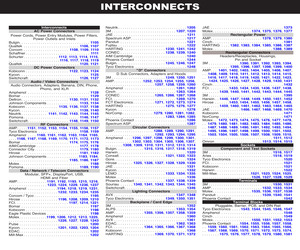
-87758-0416 538-87758-0616 538-87758-0816 538-87758-1016 538-87758-1216 538-87758-1416 538-87758-1616 538-87758-1816 538-87758-2016 538-87758-2216 538-87758-2416 538-87758-2616 538-87758-2816 538-87758-3016 538-87758-4016 538-87758-4216 538-87758-4416 538-87758-4616 538-87758-5016 Molex Part No. 87758-0416 87758-0616 87758-0816 87758-1016 87758-1216 87758-1416 87758-1616 87758-1816 87758-2016 87758-2216 87758-2416 87758-2616 87758-2816 87758-3016 87758-4016 87758-4216 87758-4416 87758-4616 87758-5016 Fig. No. of Circuits C C C C C C C C C C C C C C C C C C C 4 6 8 10 12 14 16 18 20 22 24 26 28 30 40 42 44 46 50 Dimensions: mm A 3.90 5.90 7.90 9.90 11.90 13.90 15.90 17.90 19.90 21.90 23.90 25.90 27.90 29.90 39.90 41.90 43.90 45.90 49.90 B 2.00 4.00 6.00 8.00 10.00 12.00 14.00 16.00 18.00 20.00 22.00 24.00 26.00 28.00 38.00 40.00 42.00 44.00 48.00 1 Price Each .45 .80 .92 .77 1.10 1.01 1.05 1.28 1.79 1.68 1.80 2.16 2.56 2.60 2.51 3.38 3.04 3.69 3.46 10 .393 .69 .787 .646 .983 .839 .864
 478 Pages, 106436 KB, Original
 must be changed to the PIM position (upward). The respective DIGIO signal mappings on the P1 and P2 headers are detailed in Table 2-22. Note 1: 2: In the default state, headers P1 and P2 are not assembled. These headers can each be populated with a Molex 87758-4616. The user must ensure that the EEPROM is configured in DIGIO mode. TABLE 2-22: DIGIO MODE P1 & P2 HEADER SIGNALS HBI Indexed HBI Multiplexed DIGIO P1/P2 Pin RD/RD_WR RD/RD_WR DIGIO15 P1.8 WR/ENB WR/ENB DIGIO14 P1.10 CS CS DIGIO13 P1.26 A4 - DIGIO12 P1.41 A3 - DIGIO11 P1.44 A2 ALEHI DIGIO10 P2.21 A1 ALELO OE_EXT P1.7 A0/D15 AD15 DIGIO9 P1.15 D14 AD14 DIGIO8 P1.16 D13 AD13 DIGIO7 P1.11 D12 AD12 DIGIO6 P1.12 D11 AD11 DIGIO5 P1.17 D10 AD10 DIGIO4 P1.14 D9 AD9 LATCH_IN P1.13 D8 AD8 DIGIO2 P1.19 D7 AD7 DIGIO1 P1.4 D6 AD6 DIGIO0 P1.3 D5 AD5 OUTVALID P1.22 D4 AD4 DIGIO3 P1.23 2015-2016 Microchip Technology Inc. DS50002333C-page 25 EVB-LAN9252-HBI+ EtherCAT(R) Evaluation Board User's Guide TABLE 2-22: DIGIO MODE P1 & P2 HEADER SIGNALS (CONTINU
 54 Pages, 5534 KB, Original
 must be changed to the PIM position (upward). The respective DIGIO signal mappings on the P1 and P2 headers are detailed in Table 2-22. Note 1: 2: In the default state, headers P1 and P2 are not assembled. These headers can each be populated with a Molex 87758-4616. The user must ensure that the EEPROM is configured in DIGIO mode. TABLE 2-22: DIGIO MODE P1 & P2 HEADER SIGNALS HBI Indexed HBI Multiplexed DIGIO P1/P2 Pin RD/RD_WR RD/RD_WR DIGIO15 P1.8 WR/ENB WR/ENB DIGIO14 P1.10 CS CS DIGIO13 P1.26 A4 - DIGIO12 P1.41 A3 - DIGIO11 P1.44 A2 ALEHI DIGIO10 P2.21 A1 ALELO OE_EXT P1.7 A0/D15 AD15 DIGIO9 P1.15 D14 AD14 DIGIO8 P1.16 D13 AD13 DIGIO7 P1.11 D12 AD12 DIGIO6 P1.12 D11 AD11 DIGIO5 P1.17 D10 AD10 DIGIO4 P1.14 D9 AD9 LATCH_IN P1.13 D8 AD8 DIGIO2 P1.19 D7 AD7 DIGIO1 P1.4 D6 AD6 DIGIO0 P1.3 D5 AD5 OUTVALID P1.22 D4 AD4 DIGIO3 P1.23 2015-2016 Microchip Technology Inc. DS50002333C-page 25 EVB-LAN9252-HBI+ EtherCAT(R) Evaluation Board User's Guide TABLE 2-22: DIGIO MODE P1 & P2 HEADER SIGNALS (CONTINU
 55 Pages, 5513 KB, Original
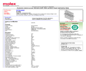
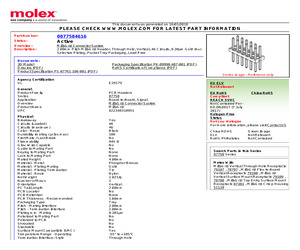
87758-4616 Active Milli-GridTM Connector System 2.00mm Pitch Milli-GridTM Header, Through Hole, Vertical, 46 Circuits, 0.38m Gold (Au) Selective Plating, Pocket Tray Packaging, Lead-Free Documents: 3D Model Drawing (PDF) Product Specification PS-87761-100 (PDF) RoHS Certificate of Compliance (PDF) Series image - Reference only Agency Certification UL E29179 General Product Family Series Application Overview Product Name UPC PCB Headers 87758 Board-to-Board, Signal Milli-GridTM Connector System Milli-GridTM 822348310951 Physical Breakaway Circuits (Loaded) Circuits (maximum) Color - Resin Durability (mating cycles max) First Mate / Last Break Flammability Glow-Wire Compliant Guide to Mating Part Keying to Mating Part Lock to Mating Part Mated Height Material - Metal Material - Plating Mating Material - Plating Termination Material - Resin Net Weight Number of Rows Orientation PC Tail Length PCB Locator PCB Retention PCB Thickness - Recommended Packaging Type Pitch - Mating Interface Pitch - Termin
 2 Pages, 36 KB, Original
487-001 PS-87761-100-001 SD-87758-107-001 This document was generated on 10/03/2018 PLEASE CHECK WWW.MOLEX.COM FOR LATEST PART INFORMATION Mouser Electronics Authorized Distributor Click to View Pricing, Inventory, Delivery & Lifecycle Information: Molex: 87758-4616
 3 Pages, 30 KB, Original
87758-4616 Active Milli-GridTM Connector System 2.00mm Pitch Milli-GridTM Header, Through Hole, Vertical, 46 Circuits, 0.38m Gold (Au) Selective Plating, Pocket Tray Packaging, Lead-Free Documents: 3D Model Drawing (PDF) Product Specification PS-87761-100 (PDF) RoHS Certificate of Compliance (PDF) Series image - Reference only Agency Certification UL E29179 General Product Family Series Application Overview Product Name PCB Headers 87758 Board-to-Board, Signal Milli-GridTM Connector System Milli-GridTM Physical Breakaway Circuits (Loaded) Circuits (maximum) Color - Resin Durability (mating cycles max) First Mate / Last Break Flammability Glow-Wire Compliant Guide to Mating Part Keying to Mating Part Lock to Mating Part Mated Height Material - Metal Material - Plating Mating Material - Plating Termination Material - Resin Number of Rows Orientation PC Tail Length PCB Locator PCB Retention PCB Thickness - Recommended Packaging Type Pitch - Mating Interface Pitch - Termination Interface Plating min
 2 Pages, 36 KB, Original


