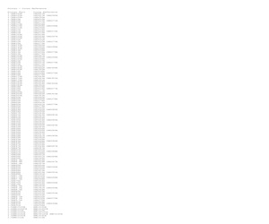
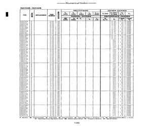
1N4106 1N5242 1N5532A/B 1N5738A/B 1N6002A/B 1N6326 1N759 1N963 1N5242 1N5242 1N5532A/B 1N5738A/B 1N5532A/B 1N5532A/B 1N6002A/B 1N5532A/B 1N6326 1N5532A/B BZX55C12 1N5738A/B 1N6002A/B 1N6002A/B 1N6326 1N6326 1N6326 1N963 1N759 1N963 BZX55C12 1N4107 1N4107 1N5243A/B 1N5533A/B 1N5739A/B 1N6003A/B 1N6327 1N964A/B 1N5243A/B 1N5243A/B 1N5533A/B 1N5739A/B 1N5243A/B 1N5533A/B 1N6003A/B 1N5533A/B 1N5739A/B 1N6003A/B 1N6003A/B 1N6327 1N6327 1N964A/B 1N4109 1N4109 1N5245A/B 1N5535A/B 1N5740A/B 1N6004A/B 1N6328 1N965A/B 1N5245A/B 1N5245A/B 1N5535A/B 1N5740A/B 1N5245A/B 1N5535A/B 1N965A/B 1N5535A/B 1N5535A/B BZX55C15 1N5740A/B 1N6004A/B 1N6004A/B 1N6328 1N6328 1N965A/B BZX55C15 1N4110 1N4110 1N5246A/B 1N5536A/B 1N5741A/B 1N6005A/B 1N6329 1N966A/B 1N4110 1N5741A/B 1N5246A/B 1N5246A/B 1N5536A/B 1N5741A/B 1N5246A/B 1N5536A/B 1N966A/B 1N5536A/B 1N5536A/B BZX55C16 1N5741A/B 1N6005A/B 1N6005A/B 1N6329 1N6329 1N966A/B BZX55C16 1N4112 1N4112 1N5248A/B 1N5538A/B 1N5742A/B 1N6006
 51 Pages, 129 KB, Original
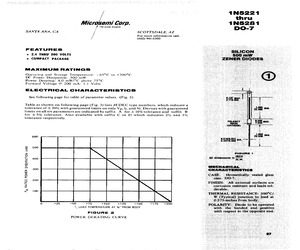
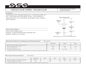
 200 0.65 2500 7000 0.1 144 152 10 +0.110 FIGURE 3 NOTE 3 Temperature coefficient (vz). Test conditions for temperature coefficient are as follows: a. Ing = 7.5 mA, Ty = 25C, T, = 125C (1N5221A, B thru 1N5242A, B.) b. Ley = Rated Ign, Ty = 25C, T. = 125C (1N5243A, B thru IN5281A, B.) Device to be temperature stabilized with current applied prior to reading breakdown voltage at the specified ambient temperature.1N5221 thru 1N5281 Do- FEATURES 4 THRU 200 VOLTS 2 e COMPACT PACKAGE *MAXIMUM RATINGS Ops C to +200C 65 Temperature: 500 mW erating and Storage DC Power Dissipation: C Power Derating: 4.0 mW/C above 75 F 1.1 Volts 00 mA: 2 orward Voltage @' STiCcS *ELECTRICAL CHARACTERI a e 2e following page for table of parameter values. (Fig. 3) able as shown on following page (Fig. 3) lists JEDEC type numbers, which indicate a T ,1,, and V. Devices with guaran- ffix A for +10% tolerance and 7 Z ith guaranteed limits on only V Jo Ww ed limits on all six parameters are indi suffix tolerance of +20' cated b
 10 Pages, 1318 KB, Scan
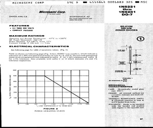
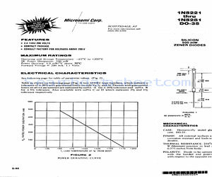
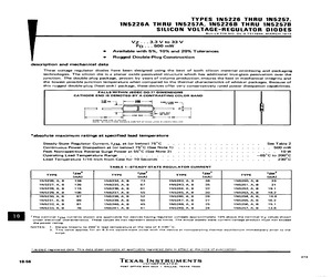
kdown curve, thereby elimi- nating unstable units. NOTE 3 Temperature coefficient (yz). Test conditions for temperature coefficient are as follows: a, Liv = 7.5 mA, Ti = 25C, T, = 125C (1N5221A, B thru 1N5242A, B.) b. Ine = Rated Ip7, T, = 25C, Ts = 125C (1N5243A, B thru 1N5281A, B.) Device to be temperature stabilized with current applied prior to reading breakdown voltage at the specified ambient temperature.MICROSEMI CORP SSE D M@@ 6115865 n0018a5 1T&5 MMSE 1N5221 thru 1N5281 DO-7 g 8 2388 8 Typical Capacitance in pF zero volts 40 At -2 volts 10 0 2 40 60 8 0 120 140 160 180 200 Zener Voltage FIGURE 4 CAPACITANCE VS. ZENER VOLTAGE (TYPICAL)S9 D MM 6115465 0001884 034 MMSE 1N5221 thru 1N5281 DO-35 MICROSEMI CORP - SANTAAN FEATURES 2.4 THRU 200 VOLTS COMPACT PACKAGE CONSULT FACTORY FOR VOLTAGES ABOVE 200 V MAXIMUM RATINGS Operating and Storage Temperature: -65C to +200C DC Power Dissipation: 500 mW Power Derating: 4.0 mW/C above 75C Forward Voltage & 200 mA: I.I Volts ELECTRICAL CHARACTERISTICS
 6 Pages, 636 KB, Scan
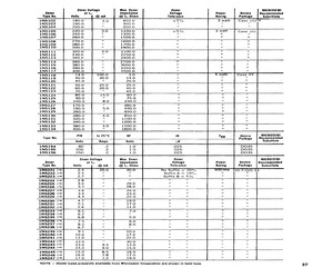
 500M 1N5240B Ss 2-32 Z2D 10%* 5.0 500M 1N5241 s 2-32 ZD 11l* 10 500M IN52414 $8 2-32 zD Li* 10 500M 1N5241B Ss 2-32 ZD 1i* 5.0 500M 1N5242 Ss 2-32 ZD 12* 10 500M 1N5242A Ss 2-32 ZD 12% 10 500M 1N5242B Ss 2-32 ZD 12* 5.0 500M 1N5243 Ss 2-32 ZD 13% 10 500M 1N5243A Ss 2-32 VAD) 13* 10 500M 1N5243B Ss 2-32 ZD 13% 5.0 500M 1N5244 Ss 2-32 ZD 14* 10 500M 1N5244A s 2-32 ZD 14* 10 500M 1N5244B Ss 2-32 ZD 14% 5.0 500M 1N5245 Ss 2-32 ZD 15* 10 500M 1N5245A Ss 2-32 ZD 15* 10 500M IN5245B Ss 2-32 ZD 15% 5.0 500M 1N5246 S 2-32 ZD 16* 10 500M 1N5246A Ss 2-32 2D 16* 10 500M 1N5246B Ss 2-32 ZD 16% 5.0 500M 1N5247 Ss 2-32 ZD L7* 10 500M 1N5247A Ss 2-32 ZD 17* 10 500M 1N5247B Ss 2-32 ZD 17* 5.0 500M 1N5248 Ss 2-32 ZD 18* 10 500M 1N5248A Ss 2-32 ZD 18* 10 500M 1N5248B Ss 2-32 ZD 18* 5.0 500M 1N5249 Ss 2-32 ZD 19% 10 500M 1N5249A S 2-32 ZD 19% 10 500M 1N5249B Ss 2-32 ZzD 19% 5.0 500M 1N5250 s 9-32 2D 20* 10 | 500M 1N5250A 8 2-32 ZzD 20% 10 500M 1N5250B s 2-32 ZD 20* 5.0 500M 1N5251 Ss 2-32 ZD 22% 10 500M 1N5251A Ss
 8 Pages, 420 KB, Scan
 200 0.65 2500 7000 0.1 144 152 10 +0.110 FIGURE 3 NOTE 3 Temperature coefficient (vz). Test conditions for temperature coefficient are as follows: a. Ing = 7.5 mA, Ty = 25C, T, = 125C (1N5221A, B thru 1N5242A, B.) b. Ley = Rated Ign, Ty = 25C, T. = 125C (1N5243A, B thru IN5281A, B.) Device to be temperature stabilized with current applied prior to reading breakdown voltage at the specified ambient temperature.1N5221 thru 1N5281 Do- FEATURES 4 THRU 200 VOLTS 2 e COMPACT PACKAGE *MAXIMUM RATINGS Ops C to +200C 65 Temperature: 500 mW erating and Storage DC Power Dissipation: C Power Derating: 4.0 mW/C above 75 F 1.1 Volts 00 mA: 2 orward Voltage @' STiCcS *ELECTRICAL CHARACTERI a e 2e following page for table of parameter values. (Fig. 3) able as shown on following page (Fig. 3) lists JEDEC type numbers, which indicate a T ,1,, and V. Devices with guaran- ffix A for +10% tolerance and 7 Z ith guaranteed limits on only V Jo Ww ed limits on all six parameters are indi suffix tolerance of +20' cated b
 9 Pages, 1272 KB, Scan
 500M 1N5240B Ss 2-32 Z2D 10%* 5.0 500M 1N5241 s 2-32 ZD 11l* 10 500M IN52414 $8 2-32 zD Li* 10 500M 1N5241B Ss 2-32 ZD 1i* 5.0 500M 1N5242 Ss 2-32 ZD 12* 10 500M 1N5242A Ss 2-32 ZD 12% 10 500M 1N5242B Ss 2-32 ZD 12* 5.0 500M 1N5243 Ss 2-32 ZD 13% 10 500M 1N5243A Ss 2-32 VAD) 13* 10 500M 1N5243B Ss 2-32 ZD 13% 5.0 500M 1N5244 Ss 2-32 ZD 14* 10 500M 1N5244A s 2-32 ZD 14* 10 500M 1N5244B Ss 2-32 ZD 14% 5.0 500M 1N5245 Ss 2-32 ZD 15* 10 500M 1N5245A Ss 2-32 ZD 15* 10 500M IN5245B Ss 2-32 ZD 15% 5.0 500M 1N5246 S 2-32 ZD 16* 10 500M 1N5246A Ss 2-32 2D 16* 10 500M 1N5246B Ss 2-32 ZD 16% 5.0 500M 1N5247 Ss 2-32 ZD L7* 10 500M 1N5247A Ss 2-32 ZD 17* 10 500M 1N5247B Ss 2-32 ZD 17* 5.0 500M 1N5248 Ss 2-32 ZD 18* 10 500M 1N5248A Ss 2-32 ZD 18* 10 500M 1N5248B Ss 2-32 ZD 18* 5.0 500M 1N5249 Ss 2-32 ZD 19% 10 500M 1N5249A S 2-32 ZD 19% 10 500M 1N5249B Ss 2-32 ZzD 19% 5.0 500M 1N5250 s 9-32 2D 20* 10 | 500M 1N5250A 8 2-32 ZzD 20% 10 500M 1N5250B s 2-32 ZD 20* 5.0 500M 1N5251 Ss 2-32 ZD 22% 10 500M 1N5251A Ss
 7 Pages, 368 KB, Scan
281 200 0.65 2500 7000 0.1 144 152 10 +0110 FIGURE 3 NOTE 3 Temperature coefficient (yz). Test conditions for temperature coefficient are as follows: a. Iny = 7.5mA, Ti = 25C, T. = 125C (1N5221A, B thru 1N5242A, B.) b. Ign = Rated Ip, T1 = 25C, Ty = 125C (1N5243A, B thru 1N5281A, B.) Device to be temperature stabilized with current applied prior to reading breakdown voltage at the specified ambient temperature. 1N5221 thru 1N5281 DO-7 Typical Capacitance in pF 338 8 g 3 10 0 At zero volts At -2 volts 20 40 60 80 100 120 40 0 180 200 Zener Voltage FIGURE 4 CAPACITANCE VS. ZENER VOLTAGE (TYPICAL)
 3 Pages, 234 KB, Scan
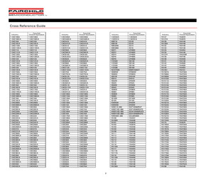
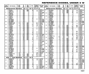
1N5235B 1N5235B 1N5236B 1N5236B 1N5236B 1N5237B 1N5237B 1N5237B 1N5238B 1N5238B 1N5238B 1N5239B 1N5239B 1N5239B 1N5240B 1N5240B 1N5240B 1N5241B 1N5241B 1N5241B Power Products Cross Reference Guide (continued) Industry 1N5242 1N5242A 1N5242B 1N5242C 1N5243 1N5243A 1N5243B 1N5243C 1N5244 1N5244A 1N5244B 1N5245 1N5245A 1N5245B 1N5246 1N5246A 1N5246B 1N5247 1N5247A 1N5247B 1N5248 1N5248A 1N5248B 1N5248C 1N5249 1N5249A 1N5249B 1N5250 1N5250A 1N5250B 1N5250C 1N5251 1N5251A 1N5251B 1N5251C 1N5252 1N5252A 1N5252B 1N5252C 1N5253 1N5253A 1N5253B 1N5254 1N5254A 1N5254B 1N5255 1N5255A 1N5255B 1N5255C 1N5256 1N5256A 1N5256B 1N5256C 1N5257 1N5257A 1N5257B 1N5257C 1N527 1N5282 1N52A Fairchild Closest Equivalent 1N5242B 1N5242B 1N5242B 1N5242C 1N5243B 1N5243B 1N5243B 1N5243C 1N5244B 1N5244B 1N5244B 1N5245B 1N5245B 1N5245B 1N5246B 1N5246B 1N5246B 1N5247B 1N5247B 1N5247B 1N5248B 1N5248B 1N5248B 1N5248C 1N5249B 1N5249B 1N5249B 1N5250B 1N5250B 1N5250B 1N5250C 1N5251B 1N5251B 1N5251B 1N5251C 1N5252B 1N5252B 1N5252B 1
 55 Pages, 404 KB, Original
down curve, thereby, elimi- nating unstable units. NOTE 3 Temperature coefficient (vz). Test conditions for temperature coefficient are as follows: a Ipr = 7.5 mA, T, = 25C, T., = 125C (1N5221A, B thru 1N5242A, B.) b. Ter = Rated Tz7, T, = 25C, T. = 125C (1N5243A, B thru 1N52814, B.) Device to be temperature stabilized with current applied prior to reading breakdown voltage at the specified ambient temperature. 5-45 1N5221 thru 1N5281 DO-35 CAPACITANCE vs. Vz CURVE TYPICAL CAPACITANCE IN PICOFARADS 0 20 -400 60 B00 120 140 180 180200 220 ZENER VOLTAGE Vz FIGURE 4 CAPACITANCE VS. ZENER VOLTAGE (TYPICAL) 5-46
 3 Pages, 155 KB, Scan
31A/B 4.7 5.1 <19 <17 <1900 <1600 1N5232A/B 5.6 <11 <1600 1N5233A/B 6.0 <7 <1600 1N5234A/B 6.2 <7 <1000 1N5235A/B 6.8 <5 <750 1N5236A/B 7.5 <6 <500 1N5237A/B 8.2 <8 <500 1N5238A/B 1N5239A/B 8.7 9.1 <8 <10 1N5240A/B 10 <17 1N5241A/B 11 <22 1N5242A/B 12 <30 1N5243A/B 13 9.5 <13 1N5244A/B 14 9.0 <15 1N5245A/B 15 8.5 1N5246A/B 1N5247A/B 16 17 7.8 7.4 1N5248A/B 18 7.0 1N5249A/B 19 6.6 <30 20 <-0.080 1.0 <-0.075 <-0.060 <+0.055 2.0 2.0 <+0.030 <+0.030 3.0 <+0.038 3.5 <+0.038 4.0 <+0.045 5.0 <+0.050 6.0 <+0.058 6.5 <+0.062 6.5 7.0 <+0.065 <+0.068 8.0 <+0.075 <2 8.4 <+0.076 <1 9.1 <+0.077 <0.5 9.9 <+0.079 10 <+0.082 <16 11 <+0.082 <17 <19 12 13 <+0.083 <+0.084 <21 14 <+0.085 <23 14 <+0.086 5 0.25 3 <600 <0.1 1N5250A/B THRU 1N5281A/B SILICON PLANAR ZENER DIODES Zener Voltage range1) Type VZNOM3) IzT Maximum zener impedance1) Maximum Reverse Leakage Current Temp Coefficient of zener voltage IR2) at VR TKVZ rZjt and rZjk at IZK V mA V %/K 1N5250A/B 20 6.2 <25 15 <-0.086 1N5251A/B 1N5252A/B 22 24 5.6 5.2 <29
 4 Pages, 278 KB, Original
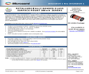
stabilize for 20 seconds. NOTE 3: Temperature coefficient (vz). Test conditions for temperature coefficient are as follows: a. IZT = 20 mA, T1 = 25 oC, T2 = 125 oC (1N5221AUR-1 & BUR-1 thru 1N5242AUR-1 & BUR-1) b. IZT = Rated IZT, T1 = 25 oC, T2 = 125 oC (1N5243AUR-1 & BUR-1 thru 1N5281AUR-1 & BUR-1) Device to be temperature stabilized with current applied prior to reading breakdown voltage at the specified ambient temperature. T4-LDS-0232-1, Rev. 1 (111957) (c)2011 Microsemi Corporation Page 4 of 6 1N5221BUR-1 thru 1N5281BUR-1 Pd, Rated Power Dissipation (mW) o o Temperature Coefifcient %/ C Temperature Coefficient mV/ C GRAPHS TEC TA TEC End Cap Temperature (C), or TA Ambient Temperature on FR4 PC Board Nominal Zener Voltage (Volts) FIGURE 2 ZENER VOLTAGE TEMPERATURE COEFFICIENT vs. ZENER VOLTAGE Typical Capacitance In Picofarads (pF) FIGURE 1 POWER DERATING CURVE Zener Voltage VZ FIGURE 3 CAPACITANCE vs. ZENER VOLTAGE (TYPICAL) T4-LDS-0232-1, Rev. 1 (111957) (c)2011 Microsemi Corporation Page
 6 Pages, 276 KB, Original
 DO-213AB 00-41 00-41 00-41 00-13 MELF-5.0 DO-213AB DO-213AB DO-213AB DO-213AB I:'U-213AIj Axial-3 AXlal-3 TO-236 SOT-23 00-7 00-35 00-35 00-35 00-35 00-3:: 00-35 00-35 00-35 00-35 00-35 00-35 00-35 00-35 00-35 Part Number 175 180 185 190 AP13.0A MLL5243A 1N5243A AP13.0 ZMM5243 1N5243 APD13.0B MLL4743A ZM4743 1N3023B 1N5566B APD13.0A MLL4743 1N3023A 1N4743 lN5566A APD13.0 lN3023 BZM85C13 MLL5928D ~tt~~~:~ lN3792B MLL5928A MLL5928 EOA03-13AB FMMZ5244 lN766-3 lN767-3 1N5534D ~~~~~!~ lN5534A lN5534 AP14.0B MLL5244B lN5244B AP14.0A MLL5244A lN5244A ~~~5~44 lN5244 EOA03-14AB lN4058 1N4058A FMMZ5245 BZX84C15 lN767-1 1N5535D lN965D lN5535C lN965C lN5535B lN5535A lN965A lN5535 lN965 AP15.0B BZV55C15 13 13 13 13 13 13 13 13 13 13 13 13 13 13 13 13 13 13 13 13 13 13 13 13 13 13.6 14 14.0 14.0 14 14 14 14 14 14 14 14 14 14 14 14 14 14 14.5 14.6 14.6 15 15 15.0 15 15 15 15 15 15 15 15 15 15 15 ~~~12;51j ~; lN5245B TZM/C15 AP15.0A MLL5245A lN5245A AP15.0 ZMM5245 1N5245 15 15 15 15 15 15 15 15 15 15 15 15 15 1
 1 Pages, 113 KB, Original
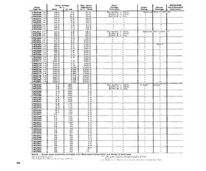
8.2 +0.062 3 500 3 11 20 6.2 6.5 1N5238A, B 8.7 +0.065 8 600 3 1,1 20 6.2 6.5 INS239A, B 9.1 +0.068 10 600 3 1.1 20 6.7 7.0 1N5240A, B 10 +0.075 7 600 3 1.1 20 7.6 8.0 1N5241A, B 11 +0.076 22 600 2 11 20 8.0 3.4 1N5242A, B 12 +0.077 30 600 1 44 20 8.7 3.1 1N5243A, B 13 +0.079 13 600 0.5 11 9.5 9.4 9.9 1N5244A, B 14 +0.082 15 600 0.1 1.1 9.0 9.5 10 1N5245A, B 15 +0.082 16 600 0.1 1.1 8.5 10.5 11 1NS246A, B 16 +0.083 7 600 0.1 1.1 78 11.4 12 1N5247A, B 17 +0.084 19 600 0.1 11 74 12.4 13 1N5248A, B 18 +0.085 21 600 0.1 11 7.0 13.3 14 1N5249A, B 19 +0.086 23 600 0.1 1.1 6.6 13.3 14 1N5250A, B 20 +0.086 25 600 0.1 1.1 6.2 14.3 15 1IN5251A, B 22 +0.087 29 600 01 1.1 5.6 16.2 17 1N5252A, B 24 +0,088 33 600 0.1 11 5.2 17.1 18 1N5253A, B 25 +0.089 35 600 0.1 11 5.0 18.1 19 1N5254A, B 27 +0.090 41 600 0.1 1.1 46 20 21 1N5225A, B 28 +0.091 44 600 0.1 11 4.5 20 21 1NS226A, B 30 +0.091 49 600 0.1 1.1 4.2] 22 23 1N5257A, B 33 +0.092 58 700 0.1 11 3.8 24 25 Suz tolerance is +10% for 1N5226A thru 1N5257A series;
 3 Pages, 106 KB, Scan
pedance with different operating currents. 3. Temperature coefficient (VZ). Test conditions for temperature coefficient are as follows: o o a. IZT = 7.5 mA, T1 = 25 C, T2 = 125 C (1N5221A, B thru 1N5242A, B). o o b. IZT = Rated IZT, T1 = 25 C, T2 = 125 C (1N5243A, B thru 1N5281A, B). (Device to be temperature stabilized with current applied prior to reading breakdown voltage at the specified ambient temp.) Copyright (c) 2005 8-09-2005 REV D Microsemi Scottsdale Division 8700 E. Thomas Rd. PO Box 1390, Scottsdale, AZ 85252 USA, (480) 941-6300, Fax: (480) 947-1503 Page 2 1N5221-1N5281B,e3 DO-35 Test Current IZT mA WWW . Microsemi .C OM JEDEC Type No. Note 1 Nominal Zener Voltage VZ @ IZT Volts 1N5221 thru 1N5281B, e3 DO-35 500 mW GLASS AXIAL-LEAD ZENER DIODES SCOTTSDALE DIVISION Pd, Rated Power Dissipation (mW) WWW . Microsemi .C OM GRAPHS TL Lead Temperature at 3/8" From Body or TA on FR4 PC Board FIGURE 1 POWER DERATING CURVE FIGURE 2 CAPACITANCE vs. ZENER VOLTAGE (TYPICAL) PACKAGE DIMENSIONS 1N5
 3 Pages, 165 KB, Original


