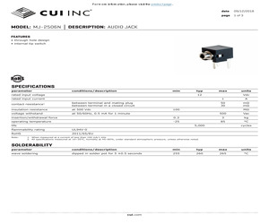
MJ-2506N DESCRIPTION: AUDIO JACK FEATURES * through hole design * internal tip switch SPECIFICATIONS parameter conditions/description min rated input voltage typ rated input current contact resistance1 between terminal and mating plug between terminal in a closed circuit insulation resistance at 500 Vdc voltage withstand at 50/60Hz, 0.5 mA for 1 minute 0.3 operating temperature -25 life 1 A 50 30 m m M 500 Vac 3 kg 85 5,000 flammability rating UL94V-0 RoHS 2011/65/EU units Vdc 100 insertion/withdrawal force Note: max 12 C cycles 1. When measured at a current of less than 100 mA/1 kHz 2. All specifications measured at 10~35C, humidity at 45~85%, under standard atmospheric pressure, unless otherwise noted. SOLDERABILITY parameter conditions/description min typ max units wave soldering dipped in solder pot for 5 0.5 seconds 255 260 265 C cui.com For more information, please visit the product page. CUI Inc MODEL: MJ-2506N DESCRIPTION: AUDIO JACK date 09/12/2018 page 2 of 3 MECHANICAL DRA
 3 Pages, 254 KB, Original
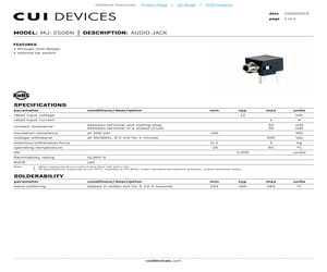
MJ-2506N DESCRIPTION: AUDIO JACK FEATURES * through hole design * internal tip switch SPECIFICATIONS parameter conditions/description min rated input voltage typ rated input current contact resistance1 between terminal and mating plug between terminal in a closed circuit insulation resistance at 500 Vdc voltage withstand at 50/60Hz, 0.5 mA for 1 minute 0.3 operating temperature -25 life 1 A 50 30 m m M 500 Vac 3 kg 85 5,000 flammability rating UL94V-0 RoHS yes units Vdc 100 insertion/withdrawal force Note: max 12 C cycles 1. When measured at a current of less than 100 mA/1 kHz 2. All specifications measured at 10~35C, humidity at 45~85%, under standard atmospheric pressure, unless otherwise noted. SOLDERABILITY parameter conditions/description min typ max units wave soldering dipped in solder pot for 5 0.5 seconds 255 260 265 C cuidevices.com Additional Resources: Product Page | 3D Model | PCB Footprint CUI Devices MODEL: MJ-2506N DESCRIPTION: AUDIO JACK date 10/04/2019 page 2 of 3 M
 3 Pages, 306 KB, Original
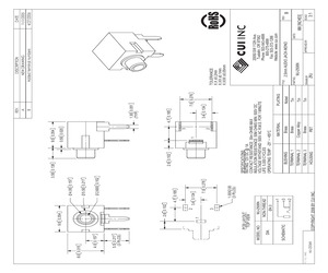
MJ-2506N PC FILE NAME: 1 3 2 MJ-2506N NON-THREAD O4.0 3 1.00X2.00 (3 PLCS) 7.0 0.276 3.4 0.134 4.7 0.185 1 2 3 0.50 0.020 9.0 0.354 7.0 0.276 3.4 0.134 4.7 0.185 1.30 0.051 (TYP) Nickel Tin Brass Brass Copper Alloy Brass PBT TERMINAL 2 TERMINAL 3 HOUSING Tin Tin PLATING MATERIAL BUSHING TERMINAL 1 SPECIFICATIONS: RATING: 12V DC @ 1A CONTACT RESISTANCE: 30m OHMS MAX INSULATION RESISTANCE: 50M OHMS MIN: 500V DC VOLTAGE WITHSTAND: 500V AC R.M.S. FOR 1 MINUTE LIFE: 5,000 CYCLES OPERATING TEMP: -25 ~ +85C 2.6 0.102 3.50 0.138 2.600 0.102 5.50 0.217 4.00 0.157 COPYRIGHT 2006 BY CUI INC. SCHEMATIC DIA. 1 2 2.6 0.102 PCB LAYOUT TOP VIEW MODEL NO. 5.5 0.217 (3 PLCS) 4.0 0.157 8.0 0.315 9.0 0.354 REV. A B ZRJ DRAWN BY: MJ-2506N APPROVED BY: UNITS: 20050 SW 112th Ave. Tualatin, OR 97062 Phone: 503-643-4899 800-275-4899 Fax: 503-372-1266 Website: www.cui.com 2.5mm AUDIO JACK-MONO PART NO. TITLE: TOLERANCE: X.X 0.2mm X.XX 0.1mm X.XXX 0.05mm DESCRIPTION NEW DRAWING Added terminal numb
 1 Pages, 167 KB, Original
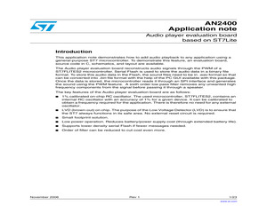
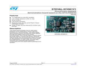
220 UF 10V PANASONIC ECE-V1AA221P OUT 2 1 C7 0.1 UF 50V CERAMIC KEMET C0805C104Z5UACTU 2 C19 0.1 UF 50V CERAMIC KEMET C0805C104Z5UACTU R11 4.7 YAEGO RC0805JR-074R7L Document Number W ednesday, June 28, 2006 Sheet 1 1 2 3 1 of 5 Rev J7 SPEAKER JACK CUI INC MJ-2506N CP-2506N-ND EXTERNAL SPEAKER 3 Voice Annunciation Evalution Board Date: Size Title 220 UF 10V PANASONIC ECE-V1AA221P C9 1 2 1 2 3 4 C16 0.01 UF 50V 10% CERAMIC AVX 08055C103KAT2A 8 7 2 1 2 U4 AUDIO AMP ST TDA7233D 2 1 2 2 C18 0.1 UF 50V CERAMIC KEMET C0805C104Z5UACTU 1 C10 100 UF 6.3V CERAMIC NICHICON UW X0J101MCL1GB 4 C15 0.01 UF 50V 10% CERAMIC AVX 08055C103KAT2A 1 2 1 2 C17 0.01 UF 50V 10% CERAMIC AVX 08055C103KAT2A R9 10K POT PANASONIC EVU-F2AF30D14 R8 10K YAEGO 9C08052A1002FKHFT 3 1 V+ GND2 3 LOW-COST LOW-PASS FILTER NOTE: DEFAULT CONFIGURATION 6TH ORDER FILTER C16 THROUGH C17 NOT INSTALLED 4 2 D C B A 5 1 6 SVR GND 1 1 2 1 2 2 3 1 D C B A 19/23 Bill of materials Appendix C Table 3. Index AN2400 Bill of materials Bill of materials
 23 Pages, 367 KB, Original
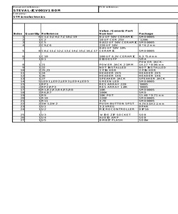
1 UF 50V CERAMIC KEMET C0805C104Z5UACTU 220 UF 10V PANASONIC ECE-V1AA221P C9 1 2 RP2 RES ARRAY 1.8K CTS 743C083182JTR 1 2 1 2 C11 0.01 UF 50V 10% CERAMIC AVX 08055C103KAT2A 1 2 4 V+ 6 SVR GND 1 GND2 3 1 2 1 2 1 3 2 EXTERNAL SPEAKER J7 SPEAKER JACK CUI INC MJ-2506N CP-2506N-ND Figure 2. APWM STEVAL-ICV001V1 Board schematic Voice annunciation: schematic 2 3/5 Revision history 2 STEVAL-ICV001V1 Revision history Table 1. 4/5 Document revision history Date Revision 21-Aug-2008 1 Changes Initial release STEVAL-ICV001V1 Please Read Carefully: Information in this document is provided solely in connection with ST products. STMicroelectronics NV and its subsidiaries ("ST") reserve the right to make changes, corrections, modifications or improvements, to this document, and the products and services described herein at any time, without notice. All ST products are sold pursuant to ST's terms and conditions of sale. Purchasers are solely responsible for the choice, selection and use of the ST products and ser
 5 Pages, 128 KB, Original
V1AA221P SMD0805 AVX 08055C103KAT2A NICHICON ST UWX0J101MCL1GB STPS140A CUI MOLEX MOLEX MOLEX MOLEX CUI INC LITEON CTS CTS YAEGO PANASONIC PANASONIC YAEGO YAEGO PANASONIC ST ST EMULATION TECHNOLOGY ST ST PJ-102B 22-28-4024 22-28-4024 10-89-1101 22-28-4064 MJ-2506N LTST-C170GKT 743C083221J 743C083182JTR 9C08052A1002FKHFT ERJ-6GEYJ104V EVU-F2AF30D14 RC0805JR-07220RL RC0805JR-074R7L EVQ-P2K02Q ST-KF33BDT ST7FLITES2Y0B6 8 9 10 11 12 13 14 15 16 17 18 19 20 21 22 23 24 1 J1 1 J2 2 J5,J3 1 J4 1 J6 1 J7 5 LED1,LED2,LED3,LED4,LED5 1 RP1 2 RP2,RP3 6 R1,R2,R3,R4,R5,R8 2 R6,R7 1 R9 1 R10 1 R11 2 SW1,SW2 1 U1 1 U2 100 UF 6.3V CERAMIC 6.3 *5.4 mm DIODESTP SMA POWER JACKPOWER JACK 2.5MM 14.17 * 8.96 mm NOT INSTALLED NOT INSTALLED 2 PIN HDR 2 PIN HDR HEADER 2X5 HEADER 2X5 HEADER 1X6 HEADER 1X6 SPEAKER JACK SPEAKER JACK GREEN LED SMD0805 RES ARRAY 220 0805 0805 RES ARRAY 1.8K 10K SMD0805 100K SMD 10K POT 11.48 * 9.71 mm 220E SMD0805 4.7E SMD0805 PUSH BUTTON SPST 4.7X3.5X2.1 mm 3.3 VREG DPAK MICROCONTROLLER DIP16
 1 Pages, 6 KB, Original
0/1,000 .65 375.00/1,000 .58 .54 .55 252.00/800 .76 433.50/1,000 .35 .35 .35 .66 .66 3 2 1 3 2 Non-threaded and Isolated Ground Shielded Version 1 Fig. 35 - SMT Power Jack NEW! Fig. 34 - SMT Power Jack 1 CUI Inc. Part No. MJ-2502 MJ1-2503A MJ-2505 MJ-2506 MJ-2506N MJ-2508 MJ-2508N MJ-2509N MJ1-2510-SMT MJ1-2510-SMT MJ-2523-SMT MJ-2523-SMT MJ-2533-SMT MJ1-2533-SMT MJ1-2533-SMT SJ1-2535-SMT SJ1-2535-SMT MJ-3502 MJ-3502N MJ1-3510-SMT MJ1-3510-SMT MJ-3523-SMT MJ-3523-SMT MJ-3536 MJ-3536N MJ-3536NG MP3-2501 MP3-3501 3 2 1 B NEW! A 100 .66 .22 .62 .28 .28 .24 .24 .26 .45 .58 .47 .50 .45 .41 .42 .58 .27 .27 .27 .51 .51 Fig. 30 - SMT Power Jack 3 2 Fig. 33 - DC Power Jack 3 2 1 1 3 2 2 B NEW! A Fig. 25 - DC Power Jack 1 1 3 2 Fig. 32 - SMT Power Jack 3 2 2 4 3 5 Fig. 28 - DC Power Jack 1 1 3 B 3 2 1 1 3 2 3 1 Fig. 24 - Right Angle Power Jack Fig. 23 - Vertical Power Jacks SMT A Fig. 20 - Male Power Jack, Open B 1 3 2 1 3 2 2 Fig. 15 - Audio Jack, Mono 3 A 3 3 2 1 Fig. 18 - Right Angle Power Jack 1 1 Ster
 3 Pages, 689 KB, Original


