31 Guide d'utilisation F 44 NL 58 P 70 Istruzioni d'uso I 84 Brugsanvisning DK 98 Bruksanvisning S 110 FIN 122 Gebruikersshandleiding Guia do utilizador Kayttoohje 1558-979A Rev. A 1 1558-979_RevA_20-06-2004_10sprog.indd 1 21-06-2004 11:29:10 English - GN 8210 user guide 1. Parts and signatures This user guide provides you with information on setting up, using and maintaining your GN 8210. Contents 1. Parts and signatures .............................................. 3 2. Product information .............................................. 3 2.1 GN 8210 - What's in the box ................................ 4 3. Setting up the GN 8210 ......................................... 3.1 Assembly .............................................................. 3.2 Clear dial tone adjustment .................................... 3.3 Microphone volume adjustment ............................ 3.4 Choosing the audio mode ..................................... 4 4 6 6 7 4. Featu
 69 Pages, 6016 KB, Original
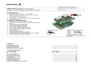
ponsible if other) ESLUOAN SEC/S ESLUOAN Approved PMR 8000 PMR 8000 series PoL series Regulator EAB/FAC/P SEC/D (Julia[Susanne You) Eriksson] 1 (1) (4) No. Checked Input 8 - 14 V, Input V, Output Output up up to to 40 A A // 210 W W 1/1301-BMR 00152-bmr6298210 629Technical 8210 UenUen Specification Date 2009-8-21 2009-09-01 Rev Reference A F A F EN/LZT 146 EN/LZT 146 411 411 R1C R1B March November 20132009 (c) Ericsson AB Key Features * * * * * * Industry standard POLATM compatible 38.61 x 25.91 x 9.64 mm (1.52 x 1.02 x 0.38 in.) High efficiency, up to. 96% Auto TrackTM sequencing pin Turbo TransTM Technology for Ultra-Fast Transient Parallel Operation General Characteristics * Operating temperature: -40C to 85C * Output over current protection (Non-latching, AutoReset) * Output short-circuit protection * Input under voltage protection * Over temperature protection * Wide output voltage adjust function * 1.5% total output voltage variation * Remote sense * On/Off inhibit control * St
 23 Pages, 867 KB, Original
ponsible if other) ESLUOAN SEC/S ESLUOAN Approved PMR 8000 PMR 8000 series PoL series Regulator EAB/FAC/P SEC/D (Julia[Susanne You) Eriksson] 1 (1) (4) No. Checked Input 8 - 14 V, Input V, Output Output up up to to 40 A A // 210 W W 1/1301-BMR 00152-bmr6298210 629Technical 8210 UenUen Specification Date 2009-8-21 2009-09-01 Rev Reference A F A F EN/LZT 146 EN/LZT 146 411 411 R1C R1B March November 20132009 (c) Ericsson AB Key Features * * * * * * Industry standard POLATM compatible 38.61 x 25.91 x 9.64 mm (1.52 x 1.02 x 0.38 in.) High efficiency, up to. 96% Auto TrackTM sequencing pin Turbo TransTM Technology for Ultra-Fast Transient Parallel Operation General Characteristics * Operating temperature: -40C to 85C * Output over current protection (Non-latching, AutoReset) * Output short-circuit protection * Input under voltage protection * Over temperature protection * Wide output voltage adjust function * 1.5% total output voltage variation * Remote sense * On/Off inhibit control * St
 22 Pages, 775 KB, Original
AO 5260 Specifications . . . . . . . . . . . . . . . . . . . . . . . . . . . . . . . 6 200 201 203 205 207 208 209 211 212 214 217 219 224 226 228 229 231 233 235 236 237 239 240 242 245 249 250 251 253 254 256 258 260 264 266 31007720 08/2016 3.9 STB DAO 8210 Digital 115/230 VAC Source Output Module (twochannel, 2 A) . . . . . . . . . . . . . . . . . . . . . . . . . . . . . . . . . . . . . . . . . . . . STB DAO 8210 Physical Description . . . . . . . . . . . . . . . . . . . . . . . . . STB DAO 8210 LED Indicators . . . . . . . . . . . . . . . . . . . . . . . . . . . . . . STB DAO 8210 Field Wiring . . . . . . . . . . . . . . . . . . . . . . . . . . . . . . . . STB DAO 8210 Functional Description . . . . . . . . . . . . . . . . . . . . . . . . STB DAO 8210 Data for the Process Image . . . . . . . . . . . . . . . . . . . . STB DAO 8210 Specifications. . . . . . . . . . . . . . . . . . . . . . . . . . . . . . . Chapter 4
 420 Pages, 3479 KB, Original
8210 and 8110S, N95 3044 page 1 of 2 Issue Date 01/01/04 The 3MTM Particulate Respirator 8210, N95 is designed to help provide quality, reliable worker protection against certain non-oil based particles. The 3MTM Particulate Respirator 8110S, N95 offers the same protection for those workers with smaller faces. The 8210 and the 8110S offer a number of benefits to you and your workers. NIOSH approved N95 * At least 95% filtration efficiency against solid and liquid aerosols that do not contain oil.* TC-84A-0007 Advanced Electret Media * Advanced electrostatically charged microfibers make breathing easier and cooler. 3MTM Particulate Respirator 8210, N95 Helps provide worker protection (Inset photo: 3MTM Particulate Respirator 8110S, N95) * Because they are comfortable to wear and easy to use, workers are Suggested Applications quick to accept and use maintenance* Grinding free respirators, like the 8210 and 8110S. Studies have shown they can * San
 3 Pages, 102 KB, Original
tems. 1-4 USING THE MODEL 8310-XX-X-XN: The Model 8311-XX-X-XN Series provides front-panel and computer control for up to 12 channels of attenuation, RF switching, or other functions. The Model 8311-XX-X-XNcombines the features of the Aeroflex / Weinschel 8210A Device Controller with a front panel user interface to form a flexible, easy to use solution. Most Model 8311-XX-X-XN Series are multi-channel configurations where RF signal is routed through either the front or rear mounted channel connector to a single or multiple Weinschel programmable attenuators thus creating a channel. For specialized configurations refer to supplemental information in the front of this manual for details. Typically Weinschel programmables are bi-directional and the RF signal can be applied to either Channel connector. Channels can be selected by selecting the front panel CHAN button. When selected, as indicated by the CHAN indicator, a new attenuation value may be entered using the INCR and DECR keys. The main displ
 65 Pages, 2228 KB, Original
s are not latched, and must be driven with a constant level to keep the desired attenuation setting. SERIAL MODE OPERATION: In the serial mode of operation, the Smartstep attenuator communicates over a two-wire serial bus to the Aeroflex / Weinschel Model 8210A Smartstep Interface. The bus uses a clock (SCL) and data (SDA) line to send and receive programming and configuration information. The messages sent over the bus use the software protocol as defined in the ACCESS.busTM V2.2 specification (Base Protocol) with Weinschel-specific extensions to support the control of step attenuators (StepAttn Protocol). These protocols and operating instructions can be located in the Model 8210A instruction manual (IM-288). The ACCESS.busTM messages have the following format: Byte# D7 D6 D5 D4 D3 D2 D1 D0 Description 1 2 3 4 Length+4 D7 S7 P D6 S6 L6 D5 S5 L5 D4 S4 L4 D3 S3 L3 D2 S2 L2 D1 S1 L1 0 0 L0 X7 X6 X5 X4 X3 X2 X1 X0 Destination address Source address Protocol flag & Msg Length msg body-
 12 Pages, 199 KB, Original
8210 - BJE @ 22\mod_1332489897340_174011.docx @ 205614 @ @ 1 Audiotulo 8210 U-500 Busch-AudioWorld(R) === Ende der Liste fur Textmarke Cover === Kayttoohje Busch-AudioWorld (R) Pos: 4 /#Neustruktur#/Online-Dokumentation (+KNX)/Inhaltsverzeichnis (--> Fur alle Dokumente <--)/Inhaltsverzeichnis @ 19\mod_1320649044386_174011.docx @ 184144 @ @ 1 1 2 3 4 5 Turvallisuus .............................................................................................................................................................. 3 Maaraysten mukainen kaytto ................................................................................................................................... 3 2.1 Ymparisto ................................................................................................................................................ 3 Tekniset tiedot.....................................................................................................................................
 8 Pages, 287 KB, Original
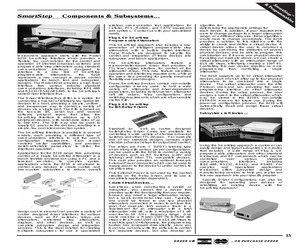
UW6WHS &RPSRQHQWV 6XEV\VWHPV wireless communication test applications for Cellular, PCS, Modem, and CATV equipment and systems. Contact us with your specialized needs. Plug & GO SmartStep Programmable Attenuators Weinschel's approach starts with the Model 8210 SmartStep Interface which provides a flexible, low cost solution for the control and operation of electromechanical switches and programmable step attenuators using standard communications interfaces. Designed to interface to a new line of SmartStep programmable attenuators, the 8210 represents a new concept in device control applications for bench test and subsystem designs. The Model 8210 provides a high-level interface from various industry standard communications interfaces, including IEEE-488 and RS232/ RS422/RS485, to the SmartStep's serial Driver Interface Bus. The Driver Interface Bus (DIB) is a system for connecting a number of relatively low-speed I/O devices to a host, providing a simple, uniform, and in
 1 Pages, 144 KB, Original
mpulse 1 2 3 4 5 6 7 8 Kabellange max 3 m Ch A Ch B Impulsgeber 1024 Impulse pro Umdrehung Hinweis! Nach Auswahl des Makros, Spannungsversorgung aus- und wieder einschalten. * * * Der Impulsgeber sollte auf der Motorwelle montiert werden. Parameter 8207 - 8210 werden je nach Applikation fur die Einstellung der Zielposition verwendet. Die beschriebenen Standardfunktionen gelten ab ACS 160 Software-Version 1.0.0.F. Standard-Parameterwerte des Applikationsmakros Positionierung: 1001 EXT 1 BEFEHLE 1 (DI1) 1201 AUSW FESTDREHZ 0 (KEINE AUSW) 1002 EXT 2 BEFEHLE 1 (DI1) 1402 RELAISAUSGANG 2 34 (POSITION ERREICHT) 1003 DREHRICHTUNG 3 (ABFRAGE) 1601 EINSCHALT FREIG 0 (KEINE AUSW) 1102 EXT1/EXT2 AUSW 2 (DI2) 1604 FEHL QUIT AUSW 6 (START/STOP) 1103 EXT SOLLW1 AUSW 1 (AI1) 2105 VORMAGN AUSW 0 (KEINE AUSW) 1106 EXT SOLLW2 AUSW 1 (AI1) 2201 BE/VERZ 1/2 AUSW 0 (KEINE AUSW) ACS 160 Betriebsanleitung 43 Start/Stop Start Start Stop Zeit Zielposition Positionszahler Zeit RelaisAusgang 2 Offen Zielpos. 1 Geschlossen
 138 Pages, 1889 KB, Original
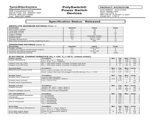
8210-2M DOCUMENT: SCD 24595 PCN: 494981-000 REV LETTER: C REV DATE: AUGUST 2, 2001 PAGE NO.: 1 OF 2 Specification Status: Released ABSOLUTE MAXIMUM RATINGS (Note 1) Parameter Max supply voltage Fault flag voltage Fault flag current Output voltage Output current Control input Storage temperature Max lead temperature during soldering (5 sec.) Symbol VIN VFLG IFLG VOUT IOUT VEN TS Value +8 +8 50 +8 Internally limited - 0.3 to +12.0 - 65 to +150 260 Units V V A V A V C C Symbol VIN IOUT TA JA Value +3 to +5.5 0.6 -40 to +85 120 Units V A C C/W OPERATING RATINGS (Note 3) Parameter Supply voltage Continuous output current (each output) Ambient operating temperature Thermal resistance (SO-8) ELECTRICAL CHARACTERISTICS (VIN = +5V; TA = 25C; unless noted.) Power switch Switch Resistance Min Output Turn-On Time Output Turn-Off Time Condition VIN = 5V, I OUT = 500mA VIN = 3.3V, I OUT = 500mA RL = 10 each output, consists of delay+rise time RL = 10 each output, consists of delay+fall time Typ 95 90 3.6 2 Max
 2 Pages, 155 KB, Original
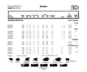
NAN: Oday REC HAIER International Diodes Ta@R Rectifier ANNIVERSARY 1647 99" FSM Case | Verm lrv@Tc Yim @lim Sour 60x Roxio Demand Outline E Number * /) WwW A) (= PCW) Number Key Standard Recovery Plastic Packages D-Pak 8EWS08S goo 88S A 8 170478 3.0 1 12 82108 HS 8EWSI2S 1700 8 (95 8 170175 3.0 1 2 82108 SEWSI6S 1600 68S 8 170-175 3.0 ho. 82108 D2Pak 1OETSO8S goo 10 10SEC 170175 2.5 1 2 82121 J4 10ETS12S 12000 10 10S 170175 25 112 82121 1OETS16S 1600 10 10510 170175 25 1 12 82121 20ETSO8S 800 20 105 Et 20 250 260 13 1 12 82102 44 20ETSI2S 1200 20: 05a sti 250 260 13 Low 82102 20ETS16S 1600-20 105s si 250 260 1.3 1 oa 82402 PowlRTab 85EPS08 g00 8589S LS 1450 1500 0.35 82139 21 85EPS12 1200 85 (95-8 1450 1500 0.35 82139 85EPSI6 1600-85 9S LAS 1450 1500 0.38 82139 TO-220AC (2-pin) 10ETSO8 goo 0 tS a0 170175 25 2 82120 JIOA 10ETS12 1200 10-105 170175 2.5 12 82120 1OETS16 1600 10 105i sO 10175 25 12 82120 20ETS08 FT 250 260 13 12 8210]
 1 Pages, 29 KB, Scan
h) (RIDR4; n028h) . . . . . . . . . . . . . . . . . . . . . . . . . . . . . . . . . . . 4.2.2.5 OC Descriptors (OCD; n400h, n408h...n7F0h, n7F8h) . . . . . . . . 4.2.2.6 E-RAM Indirect Data Register Set (EIDR0; 8200h) (EIDR2; 8208h) (EIDR2; 8208h) (EIDR4; 8210h) (EIDR6; 8218h) . . . . . . . . . . . . . . . . . . . . . . . . . . . . . . . . . . . 4.2.2.7 E-RAM Indirect Command Register (EICR; 8220h) . . . . . . . . . . 4.2.2.8 E-RAM Indirect Address Register (EIAR; 8228h) . . . . . . . . . . . . 4.2.2.9 E-RAM Configuration Register (ECR; 8230h) . . . . . . . . . . . . . . 4.2.2.10 Interrupt Enable Register (IER; 8238h) . . . . . . . . . . . . . . . . . . . Proprietary and Confidential to PMC-Sierra, Inc and for its Customers' Internal Use Document ID: PMC-2010146, Issue 4 85 88 91 94 96 97 99 7 PM2329 ClassiPI Network Classification Processor Datasheet Status Register (STSR; 8240h) . . . . . . . . . . . . . . . . Operation Control Register (OPCR; 8248h) . . . . . . . Channel Assignment Register (C
 162 Pages, 812 KB, Original
 UM10211 NXP Semiconductors Chapter 5: LPC2300 EMC Table 46. EMC register summary Address Register Name Description Warm POR Type Reset Reset Value Value 0xFFE0 820C EMCStaticWaitRd0 Selects the delay from chip select 0 to a read access. - 0x1F R/W 0xFFE0 8210 EMCStaticWaitPage0 Selects the delay for asynchronous page mode sequential accesses for chip select 0. - 0x1F R/W 0xFFE0 8214 EMCStaticWaitWr0 Selects the delay from chip select 0 to a write access. - 0x1F R/W 0xFFE0 8218 EMCStaticWaitTurn0 Selects the number of bus turnaround cycles for chip select 0. - 0xF R/W 0xFFE0 8220 EMCStaticConfig1 Selects the memory configuration for static chip select 1. - 0x0 R/W 0xFFE0 8224 EMCStatic\WaitWen1 Selects the delay from chip select 1 to write enable. - 0x0 R/W 0xFFE0 8228 EMCStaticWaitOen1 Selects the delay from chip select 1 or address change, whichever is later, to output enable. - 0x0 R/W 0xFFE0 822C EMCStaticWaitRd1 Selects the delay from chip select 1 to a read access. - 0x1F R/W 0xFFE0 8230 EM
 613 Pages, 3461 KB, Original
enable. - 0x0 R/W 0xFFE0 8208 EMCStatic WaitOen0 Selects the delay from chip select 0 or address change, whichever is later, to output enable. - 0x0 R/W 0xFFE0 820C EMCStatic WaitRd0 Selects the delay from chip select 0 to a read access. - 0x1F R/W 0xFFE0 8210 EMCStatic WaitPage0 Selects the delay for asynchronous page mode sequential accesses for chip select 0. - 0x1F R/W 0xFFE0 8214 EMCStatic WaitWr0 Selects the delay from chip select 0 to a write access. - 0x1F R/W 0xFFE0 8218 EMCStatic WaitTurn0 Selects the number of bus turnaround cycles for chip select 0. - 0xF R/W 0xFFE0 8220 EMCStatic Config1 Selects the memory configuration for static chip select 1. - 0x0 R/W 0xFFE0 8224 EMCStatic WaitWen1 Selects the delay from chip select 1 to write enable. - 0x0 R/W 0xFFE0 8228 EMCStatic WaitOen1 Selects the delay from chip select 1 or address change, whichever is later, to output enable. - 0x0 R/W 0xFFE0 822C EMCStatic WaitRd1 Selects the delay from chip select 1 to a read access. - 0x1F R/W 0xFFE0 8
 792 Pages, 4173 KB, Original


