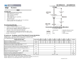
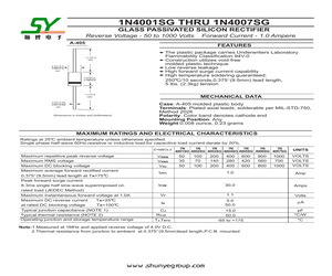
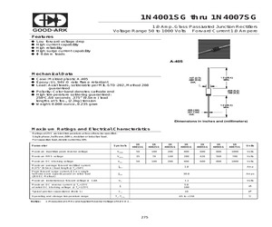
1N4001SG THRU 1N4007SG 1.0 AMP. Glass Passivated Rectifiers Voltage Range 50 to 1000 Volts Current 1.0 Ampere A-405 Features a a a a a Low forward voltage drop High current capability High reliability High surge current capability O 0.6mm leads Mechanical Data a a a a a a Cases: Molded plastic Epoxy: UL 94V-0 rate flame retardant Lead: Axial leads, solderable per MIL-STDLead: 202, Method 208 guaranteed Polarity: Color band denotes cathode end High temperature soldering guaranteed: 250C/10 seconds/.375",(9.5mm) lead lengths at 5 lbs.,(2.3kg) tension Weight: 0.22 gram Dimensions in inches and (millimeters) Maximum Ratings and Electrical Characteristics Rating at 25C ambient temperature unless otherwise specified. Single phase, half wave, 60 Hz, resistive or inductive load. For capacitive load, derate current by 20% Type Number Maximum Recurrent Peak Reverse Voltage Maximum RMS Voltage Maximum DC Blocking Voltage Maximum Average Forward Rectified Current .375"(9.5mm) Lead Length @TA = 50C Peak Forwa
 2 Pages, 44 KB, Original
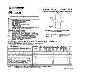
1N4001SG THRU 1N4007SG 1.0 AMP. Glass Passivated Rectifiers Voltage Range 50 to 1000 Volts Current 1.0 Ampere A-405 Features a Low forward voltage drop a High current capability a High reliability aHigh surge current capability a0.6mm leads Mechanical Data a Cases: Molded plastic a Epoxy: UL 94V-0 rate flame retardant a Lead: Axial leads, solderable per MIL-STD202, Method 208 guaranteed a Polarity: Color band denotes cathode end a High temperature soldering guaranteed: 260/10 seconds/.375",(9.5mm) lead lengths at 5 lbs.,(2.3kg) tension aWeight: 0.22 gram Dimensions in inches and (millimeters) Maximum Ratings and Electrical Characteristics Rating at 25ambient temperature unless otherwise specified. Single phase, half wave, 60 Hz, resistive or inductive load. For capacitive load, derate current by 20% 1N 1N Symbol 4001SG Type Number 4002SG Maximum Recurrent Peak Reverse Voltage Maximum RMS Voltage Maximum DC Blocking Voltage Maximum Average Forward Rectified Current .375" (9.5mm) Lead Length @TA =
 2 Pages, 49 KB, Original
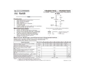
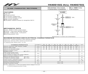
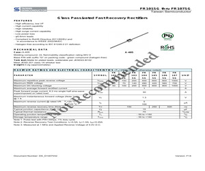
1N4001SG - 1N4007SG 1.0 AMP. Glass Passivated Rectifiers A-405 Features Glass passivated chip junction. High efficiency, Low VF High current capability High reliability High surge current capability Low power loss 0.6mm leads Mechanical Data Cases: Molded plastic Epoxy: UL 94V-0 rate flame retardant Lead: Pure tin plated, lead free., solderable per MIL-STD-202, Method 208 guaranteed Polarity: Color band denotes cathode High temperature soldering guaranteed: o 260 C /10 seconds/.375",(9.5mm) lead lengths at 5 lbs.,(2.3kg) tension Weight: 0.22 gram Dimensions in inches and (millimeters) Maximum Ratings and Electrical Characteristics Rating at 25 oC ambient temperature unless otherwise specified. Single phase, half wave, 60 Hz, resistive or inductive load. For capacitive load, derate current by 20% Type Number Symbol Maximum Recurrent Peak Reverse Voltage Maximum RMS Voltage Maximum DC Blocking Voltage Maximum Average Forward Rectified Current .375" (9.5mm) Lead Length @TA = 50 oC Peak Forward Surge
 2 Pages, 164 KB, Original
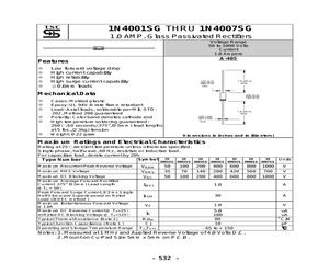
rdant Lead: Pure tin plated, lead free., solderable per MIL-STD-202, Method 208 guaranteed Polarity: Color band denotes cathode High temperature soldering guaranteed: 260 C /10 seconds/.375,(9.5mm) lead lengths at 5 Ibs.,(2.3kg) tension Weight: 0.22 grams 1N4001SG - 1N4007SG 1.0 AMP. Glass Passivated Rectifiers A-405 107 (2.7) .080 (20) DIA. 1.0 (25.4) I (205 (5.2) "166 (4.2) 1.0 (25.4) MIN. 53) >| ~<__ Dimensions in inches and (millimeters) Marking Diagram 11N400XSG| SGYWw 1N400XSG = Specific Device Code G Y Www = Green Compound = Year = Work Week Maximum Ratings and Electrical Characteristics Rating at 25C ambient temperature unless otherwise specified. Single phase, half wave, 60 Hz, resistive or inductive load. For capacitive load, derate current by 20% 1N 1N 1N 1IN 1N 1N IN . Type Number Symbol 491sc140028c|40038c|40048G|4005Sc|4006sc|4007sc|Units Maximum Recurrent Peak Reverse Voltage VRRM | 50 | 100 | 200 | 400 | 600 | 800 | 1000} V Maximum RMS Voltage Vrous | 35 70 | 140 | 280 | 420 | 560
 2 Pages, 424 KB, Scan
1N4001SG thru 1N4007SG 1.0 Amp. Glass Passivated Junction Rectifiers SYNSEMI SEMICONDUCTOR Voltage Range 50 to 1000 Volts Forward Current 1.0 Ampere Features @ Low fonward voltage drap @ High current capability @ High reliability @ High surge current capability @ 306mm leads A-405 Mechanical Data # Case: Molded plastic A-405 Moen, wa" @ Epoxy: UL 94-0 rate flame retardant DIA. @ Lead: Axial leads, solderable per MIL-STD-202, Method 208 Le | ae guaranteed 7 @ Polarity: Color band denotes cathode end i ee? @ High temperature soldering guaranteed: 3 250C/10 secands .375 (9.5mm) lead lengths at Slbs., (2.3kq) tension @ Weight: 0.008 ounce, 0.235 gram 4.0 (25.4) MIN. 025 (.64} 021 (.53)) tome joo: DIA. | Dimensions in inches and (millimeters) Maximum Ratings and Electrical Characteristics Ratings at 26C ambient temperature unless othenwvise specified. Single phase, half wave, 60Hz, resistive or indudive bad. For capacitive load, derate current by 2056 1N 1N 1N 1N 1N 1N 1N . Paenete! Symbols | noise |
 2 Pages, 311 KB, Scan
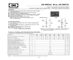
1N4001SG - 1N4007SG CREAT BY ART Pb 1.0 AMP. Glass Passivated Rectifiers A-405 RoHS COMPLIANCE Features Glass passivated chip junction High efficiency, Low VF High current capability High reliability High surge current capability Low power loss 0.6mm leads Green compound with suffix "G" on packing code & prefix "G" on datecode Mechanical Data Cases: Molded plastic Epoxy: UL 94V-0 rate flame retardant Dimensions in inches and (millimeters) Marking Diagram Lead: Pure tin plated, lead free, solderable per MIL-STD-202, Method 208 guaranteed Polarity: Color band denotes cathode 1N400XSG = Specific Device Code High temperature soldering guaranteed: 260/10s /.375", (9.5mm) lead lengths at 5 lbs, (2.3kg) tension G = Green Compound Y = Year WW = Work Week Weight: 0.22 grams Maximum Ratings and Electrical Characteristics Rating at 25 ambient temperature unless otherwise specified. Single phase, half wave, 60 Hz, resistive or inductive load. For capacitive load, derate current by 20% Type Number Symbol 1N 1
 2 Pages, 184 KB, Original
eatures $$$$ooos Glass passivated chip junction. High efficiency, Low VF High current capability High reliability High surge current capability Low power loss 0.6mm leads Green compound with suffix G on packing code & prefix G on datecode. Mechanical Data 1N4001SG - 1N4007SG 1.0 AMP. Glass Passivated Rectifiers 107 (2.7) 1.0 (25.4) 080 (2.0) MIN. DIA. | Lotfi oy U 205 (5.2) 166 (4.2) 1.0 (25.4) MIN. 025 (64 .021 (.53) tomm beam DIA. Dimensions in inches and (millimeters) ~ Cases: Molded plastic Marking Diagram ~+ Epoxy: UL 94V-0 rate flame retardant ~ Lead: Pure tin plated, lead free., solderable per MIL-STD-202, Method 208 guaranteed 1M400XSG = Specific Device Code + Polarity: Color band denotes cathode jwoxsq S = Green Compound ~ High temperature soldering guaranteed: Sovwy WW - Woe Week 260C /10 seconds/.375,(9.5mm) lead lengths at 5 Ibs.,(2.3kg) tension + Weight: 0.22 gram Maximum Ratings and Electrical Characteristics Rating at 25C ambient temperature unless otherwise specified. Single phase
 2 Pages, 37 KB, Scan
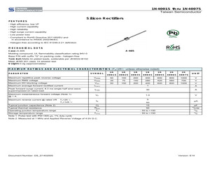
1N4001SG thru 1N4007SG REVERSE VOLTAGE - 50 to 1000 Volts FORWARD CURRENT - 1.0 Ampere GLASS PASSIVATED RECTIFIERS A-405 FEATURES Low cost Diffused junction Low forward voltage drop Low reverse leakage current 1.0(25.4) MIN. High current capability The plastic material carries UL recognition 94V-0 .028(0.7) .020(0.5) DIA. .205(5.2) MAX .107(2.7) DIA. .080(2.0) MECHANICAL DATA Case: JEDEC A-405 molded plastic 1.0(25.4) MIN. Polarity: Color band denotes cathode Weight: 0.008 ounces , 0.22 grams Mounting position :Any Dimensions in inches and (millimeters) MAXIMUM RATINGS AND ELECTRICAL CHARACTERISTICS Rating at 25 ambient temperature unless otherwise specified. Single phase, half wave ,60Hz, resistive or inductive load. For capacitive load, derate current by 20% SYMBOL 1N 4001SG 1N 4002SG 1N 4003SG 1N 4004SG 1N 4005SG 1N 4006SG 1N 4007SG UNIT Maximum Recurrent Peak Reverse Voltage VRRM 50 100 200 400 600 800 1000 V Maximum RMS Voltage VRMS 35 70 140 280 420 560 700 V VDC 50 100 200 400 600 800 1000
 2 Pages, 82 KB, Original
1N4001SG THRU 1N4007SG 1.0 AMP. Glass Passivated Rectifiers Voltage Range 50 to 1000 Volts Current 1.0 Ampere A-405 Features Low forward voltage drop High current capability High reliability High surge current capability 0.6mm leads Mechanical Data Cases: Molded plastic Epoxy: UL 94V-0 rate flame retardant Lead: Axial leads, solderable per MIL-STD202, Method 208 guaranteed Polarity: Color band denotes cathode end High temperature soldering guaranteed: 260/10 seconds/.375",(9.5mm) lead lengths at 5 lbs.,(2.3kg) tension Weight: 0.22 gram Dimensions in inches and (millimeters) Maximum Ratings and Electrical Characteristics Rating at 25ambient temperature unless otherwise specified. Single phase, half wave, 60 Hz, resistive or inductive load. For capacitive load, derate current by 20% 1N Symbol 1N Type Number 1N 1N 1N 1N 1N 4001SG 4002SG 4003SG 4004SG 4005SG 4006SG 4007SG Maximum Recurrent Peak Reverse Voltage Maximum RMS Voltage Maximum DC Blocking Voltage Maximum Average Forward Rectified Current .
 2 Pages, 49 KB, Original
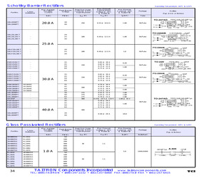
A 0.72 @ 20 A 0.72 @ 20 A 0.20 50/Tube 1.00 0.20 50/Tube 1.00 1.00 5.00 1.00 1.00 1.00 1.00 @ 35 V 30/Tube 1.00 400 30 40 0.58 @ 20 A 10.0 Glass Passivated Rectifiers Part No. CrossReference Max. Average Rectified Current Peak Inverse Voltage lo(A) PIV(V) 1N4001SG RL101G 50 1N4002SG RL102G 100 1N4003SG RL103G 200 1N4004SG RL104G 400 1N4005SG RL105G 600 1N4006SG RL106G 800 1N4007SG RL107G 1000 RL101G 1N4001SG RL102G 1N4002SG 100 RL103G 1N4003SG 200 RL104G 1N4004SG 400 RL105G 1N4005SG 600 RL106G 1N4006SG 800 RL107G 1N4007SG 1000 34 1.0 A Operating Temperature: -65o C to 125o C Peak Fwd. Surge Current @ 8.3 ms Superimposed Max. Forward Voltage @ 25o C @ Rated Io Max. Reverse Current @ 25oC @ Rated PIV Package lFSM (A) V FM(V) I R(A) Bulk/Reel 30 1.1 5.0 1000/5000 50 50 Outline (Typ. in Inches) 1.1 TAITRON Components Incorporated www.taitroncomponents.com TEL: (800) TAITRON * (800) 247-2232 * (661) 257-6060 FAX: (800) TAIT-FAX * (661) 257-6415
 1 Pages, 23 KB, Original
1N4001SG THRU 1N4007SG GLASS PASSIVATED SILICON RECTIFIER Reverse Voltage - 50 to 1000 Volts Forward Current - 1.0 Ampere A-405 FEATURES The plastic package carries Underwriters Laboratory Flammability Classification 94V-0 Construction utilizes void-free molded plastic technique Low reverse leakage High forward surge current capability High temperature soldering guaranteed: 250 C/10 seconds,0.375"(9.5mm) lead length, 5 lbs. (2.3kg) tension 1.0 (25.4) MIN. 0.107 (2.7) 0.080 (2.3) DIA. 0.205(5.2) 0.166(4.2) 1.0 (25.4) MIN. MECHANICAL DATA 0.025 (0.65) 0.021 (0.55) DIA. Case: A-405 molded plastic body Terminals: Plated axial leads, solderable per MIL-STD-750, Method 2026 Polarity: Color band denotes cathode end Mounting Position: Any Weight:0.008 ounce, 0.23 grams Dimensions in inches and (millimeters) MAXIMUM RATINGS AND ELECTRICAL CHARACTERISTICS Ratings at 25 C ambient temperature unless otherwise specified. Single phase half-wave 60Hz,resistive or inductive load,for capacitive load current derat
 2 Pages, 422 KB, Original
 to fully indemnify TSC for any damages resulting from such improper use or sale. Document Number: DS_D1401031 Version: E14 Mouser Electronics Authorized Distributor Click to View Pricing, Inventory, Delivery & Lifecycle Information: Taiwan Semiconductor: 1N4001SG 1N4002SG 1N4003SG 1N4004SG 1N4005SG 1N4006SG 1N4007SG
 5 Pages, 196 KB, Original
.70 0.079 0.106 B 0.53 0.64 0.021 0.025 C 25.40 - 1.000 - D 4.20 5.20 0.165 0.205 E 25.40 - 1.000 - tR e co mm en Min No MARKING DIAGRAM P/N = Specific Device Code G= Green Compound YWW = Date Code F= Document Number: DS_D1407032 Factory Code Version: F14 1N4001SG thru 1N4007SG Taiwan Semiconductor No tR e co mm en de d CREAT BY ART Notice Specifications of the products displayed herein are subject to change without notice. TSC or anyone on its behalf, assumes no responsibility or liability for any errors inaccuracies. Information contained herein is intended to provide a product description only. No license, express or implied,to any intellectual property rights is granted by this document. Except as provided in TSC's terms and conditions of sale for such products, TSC assumes no liability whatsoever, and disclaims any express or implied warranty, relating to sale and/or use of TSC products including liability or warranties relating to fitness for a particular purpose, merchantability, or infrin
 5 Pages, 371 KB, Original
1N4001SG thru 1N4007SG 1.0 Amp. Glass Passivated Junction Rectifiers Voltage Range 50 to 1000 Volts Forward Current 1.0 Ampere Features Low forward voltage drop High current capability High reliability High surge current capability 0.6mm leads Mechanical Data Case: Molded plastic A-405 Epoxy: UL 94V-O rate flame retardant Lead: Axial leads, solderable per MIL-STD-202, Method 208 guaranteed Polarity: Color band denotes cathode end High temperature soldering guaranteed: 250oC/10 seconds .375" (9.5mm) lead lengths at 5 lbs., (2.3kg) tension Weight: 0.008 ounce, 0.235 gram Maximum Ratings and Electrical Characteristics Ratings at 25oC ambient temperature unless otherwise specified. Single phase, half wave, 60Hz, resistive or inductive load. For capacitive load, derate current by 20% Symbols 1N 4001S G 1N 4002S G 1N 4003S G 1N 4004S G Maximum repetitive peak reverse voltage VRRM 50 100 200 Maximum RMS voltage VRMS 35 70 140 Maximum DC blocking voltage V DC 50 100 200 Maximum average forward rectified
 2 Pages, 498 KB, Original
ial leads, solderable per MIL-STD-750, Method 2026 Polarity: Color band denotes cathode end Mounting Position: Any Weight: DO-41 - 0.012 ounce, 0.335 gram A-405 - 0.008 ounce, 0.235 gram Note: Lead diameter is 0.025(0.64)/0.021(0.53) for part numbers from 1N4001SG thru 1N4007SG Maximum Ratings and Electrical Characteristics Ratings at 25oC ambient temperature unless otherwise specified. Symbols 1N 4001G 1N 4002G 1N 4003G 1N 4004G Maximum repetitive peak reverse voltage VRRM 50 100 200 Maximum RMS voltage VRMS 35 70 140 Maximum DC blocking voltage V DC 50 100 200 Maximum average forward rectified current 0.375" (9.5mm) lead length at TA=75oC IF(AV) 1.0 Amp Peak forward surge current 8.3ms single half sine-wave superimposed on rated load (JEDEC Method) IFSM 30.0 Amps Maximum full load reverse current, full cycle average 0.375" (9.5mm) lead length TA=75oC IR(AV) 30 uA VF 1.1 Volts IR 5.0 50 uA trr 1.0 uS pF Parameter Maximum instantaneous forward voltage at 1.0A Maximum DC reverse current at rated D
 2 Pages, 176 KB, Original


