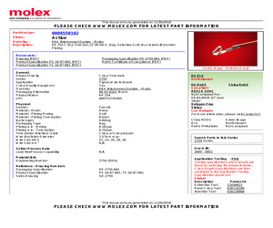
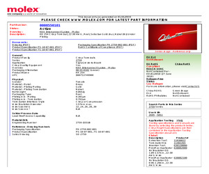
[Feb-07-2003 2:19:37 PM] Terminals P/N - 08-55-0101 E-mail this page to a friend [ (c) Copyright 2002 Molex Incorporated ] file:///G|/imaging/BITTING/HTML_CLUB/20030207/02062003/MOLE/02062003/008550101.htm (2 of 2) [Feb-07-2003 2:19:37 PM] Terminals P/N - 08-55-0102 English Spanish French Italian German Chinese (simplified) Japanese Korean Datasheet Terminals P/N KK(R) Crimp Terminal 2759, 22-30 AWG, Bag, Brass Selective Gold (Au) [ Home > Products > Terminals P/N > Datasheet ] Help 08-55-0102 Product Name KK(R) Molex Series 2759 Gender Wire Size [AWG] Wire Insulation Diameter-max Packaging Plating Contact Female 24, 22, 26, 30, 28 1.57mm (.062") Bag Gold (Au) Selective Plating Thickness 0.38m (15") Contact Material Brass (CuZn) Termination 990 Catalog Page MX01 Catalog Page Marketing Series and Version Related Products Application Tooling Part Number Region Product Description Link:Good Crimps 11-01-0185 Americas Hand Crimper J-30 11-03-0022 Americas Extraction Tool C-110 63812-0000
 14 Pages, 298 KB, Original
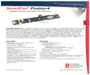
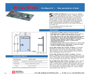
sing 4 Terminal (tin) 6 Housing 18 Terminal (gold) 1 Housing 12 Terminal (gold) 1 Housing 6 5 Mounting Hardware 1 1 1 1 Terminal (gold) PCB Support Aluminum Spacer Screw Nut J3 + A - Molex No. 09-50-8041 Molex No. 08-50-0106 Molex No. 22-01-3037 Molex No. 08-55-0102 Molex No. 22-01-3127 Molex No. 08-55-0102 Molex No. 22-01-3067 Molex No. 08-55-0102 Richco No. CBS-4-19 Richco No. ALSS6-2 6-32 x 5/8 6-32 J6 + A - J12 SCL C1 SDA D1 External Thermistor 7 6 5 Fan Connection to Headers J3-J6 Alarm Contact INCORPORATED SDA D0 5 CONTROL RESOURCES SCL C0 Input Power Connection to Header J1 Refer to Figure 1.0 for input power wiring. One or two power supplies in the range of 36 - 75 VDC should be connected at header J1. The Fusion-4 can supply up to 3.0 Amps (still air) at 24 VDC to the fan load at 55C. Less than Nine Fans: Through the I2C, each fan header may be disabled. When disabled, the alarm outputs associated with that fan header will always show no alarm. 3.3VDC GND Or equ
 8 Pages, 264 KB, Original
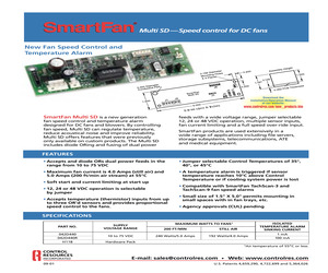
y 1 4 1 2 1 2 1 2 1 6 4 Mounting Hardware 1 1 1 1 Description Mfg. & Part No.1 Molex No. 09-50-8041 Terminal Molex No. (Tin) 08-50-0106 Molex No. Housing 09-50-8021 Terminal Molex No. (Tin) 08-50-0106 Molex No. Housing 22-01-2027 Terminal Molex No. (gold) 08-55-0102 Molex No. Housing 22-01-2027 Terminal Molex No. (gold) 08-55-0102 Molex No. Housing 22-01-3067 Terminal Molex No. (gold) 08-55-0102 Richco No. PCB Support CBS-4-19 Aluminum Richco No. Spacer ALSS6-2 Screw, 6-32x5/8" Nut, 6-32 Housing Or equivalent Input Power Connection to header J1 Refer to Figure 1.0 for input power wiring. One or two power supplies in the range of 30 to 75 VDC should be connected at header J1. If two power supplies are used, they are logically OR'd on the Multi-SD so that the operating voltage is equal to the higher of the two supplies. An OR'ing diode is located in the A & B power supply legs. The Multi-SD can supply up to 4.0 Amps (still air) and 5.0 Amps (200 LFPM air stream) at 12, 24
 6 Pages, 158 KB, Original
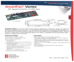
ROL RESOURCES INCORPORATED 1 Molex No. 26-60-4020 Molex No. 22-29-2041 1 Housing 2 Terminal (Tin) 4 Housing 12 Terminal (gold) 1 Housing 8 Terminal (gold) 1 Housing 4 Terminal (gold) Molex No. 09-50-8021 Molex No. 08-50-0106 Molex No. 22-01-3037 Molex No. 08-55-0102 Molex No. 22-01-3087 Molex No. 08-55-0102 Molex No. 22-01-3047 Molex No. 08-55-0102 Or equivalent Input Power Connection to Header J5 Refer to Figure 1.0 for input power wiring. One power supply in the range of 12 VDC +/- 20% should be connected at header J5. The Vortex can supply up to 5.0 Amps (still air) at 12 VDC to the fan load. Fan Connection to Headers J1-J4 Four Fans: The Vortex distributes power to and monitors the tachometer signals from four three-wire fans. Referring to Figure 1.0, connect the fans to headers J1 through J4. Fan wires are usually color coded with red for +, black or blue for - and white or yellow for tachometer signal. Fan current at each fan header must not exceed 4.0 Amps. Total
 6 Pages, 180 KB, Original
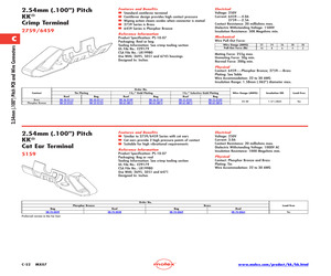
 .227 .181 .393 .262 .21 .239 .235 .223 .507 .332 .27 .568 .375 .297 .621 .416 .332 .673 .445 .363 .100" CRIMP TERMINALS *Wire gauge: 22-30 AWG *For use with Fig. A *RoHS Compliant per Molex documentation MOUSER STOCK NO. 538-08-50-0114 538-08-56-0110 538-08-55-0102 538-08-52-0123 538-08-65-0814 538-08-65-0816 Molex Part No. 08-50-0114 08-56-0110 08-55-0102 08-52-0123 08-65-0814 08-65-0816 Gold (Au) is gold * Select only on the mating area Fig. Contact E E E E E E Brass Brass Brass Phos. Bronze Phos. Bronze Phos. Bronze For quantities of 1000 and up, call for quote. Tin Plating - Bottom Entry 538-22-14-2024 22-14-2024 B 2 4.98 2.54 .29 538-22-14-2034 22-14-2034 B 3 7.52 5.08 .39 538-22-14-2044 22-14-2044 B 4 10.06 7.62 .58 538-22-14-2054 22-14-2054 B 5 12.60 10.16 .72 538-22-14-2064 22-14-2064 B 6 15.14 12.70 .86 538-22-14-2074 22-14-2074 B 7 17.68 15.24 1.01 538-22-14-2084 22-14-2084 B 8 20.22 17.78 1.03 538-22-14-2094 22-14-2094 B 9 22.76 20.32 1.29 538-22-14-2104 22-14-2104 B 10 2
 478 Pages, 106436 KB, Original
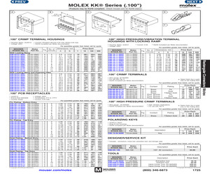
 .108 .134 .176 .178 .213 .239 .269 .281 .307 500 .084 .085 .084 .105 .14 .142 .17 .19 .214 .221 .241 Gold (Au) is gold * Select only on the mating area For quantities greater than listed, call for quote. MOUSER STOCK NO. 538-08-50-0114 538-08-56-0110 538-08-55-0102 538-08-52-0123 538-08-65-0814 538-08-65-0816 Molex Part No. 08-50-0114 08-56-0110 08-55-0102 08-52-0123 08-65-0814 08-65-0816 Price Each Fig. Contact Plating E E E E E E Brass Brass Brass Phos. Bronze Phos. Bronze Phos. Bronze Tin Gold Select * Tin Gold Gold *Select Gold 1 .15 .35 .23 .17 .74 .25 100 .095 .224 .16 .108 .523 .162 500 .091 .178 .145 .084 .411 .129 .100" HIGH PRESSURE CRIMP TERMINALS * Wire gauge: 22-30AWG * RoHS Compliant per Molex documentation * High vibration applications. * For use with Fig. D Gold (Au) is gold * Select only on the mating area For quantities greater than listed, call for quote. MOUSER STOCK NO. 538-08-55-0129 Molex Part No. 08-55-0129 Price Each Fig. Contact Plating F Brass *Select Gold
 1 Pages, 480 KB, Original
 Note: L is positive (+); NC and NO are negative (-). Alarm Circuit Logic Suggested Connecting Hardware Ref. Header on Board1 Desc. J2 22-29-2021 J3 22-29-2071 Qty H109 Hardware Pack Desc. Mfg.1 Part No.1 1 2 Molex Housing Terminal (gold) Molex 22-01-2027 08-55-0102 1 7 Molex Housing Terminal (gold) Molex 22-01-3077 08-55-0102 2 PCB Support Richco Below Temperature Trigger Alarm Output Above Temperature Trigger NC Open Circuit NO Short to Ground Open Circuit Open Circuit C-E Open Circuit Short to Ground Open Circuit Short to Ground Power Removed from Unit Open Circuit CBS-4-19 1 or equivalent CONTROL RESOURCES INCORPORATED E-mail: sales@controlres.com Web: www.controlres.com 51
 2 Pages, 104 KB, Original
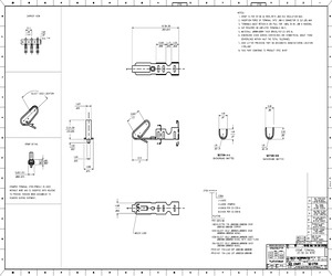
S DRAWING CONTAINS INFORMATION THAT IS PROPRIETARY TO MOLEX AW2 [& WITHIN DIMENSIONS INCORPORATED AND SHOULD NOT BE USED WITHOUT WRITTEN PERMISSION| Ls G Ze . s v 6 & " B 2 1 2 8 7 6 | 5 | 4 | 3 | 2 | 1 2759-(###)* PART NO, ENG. NO. 08-55-010| 2759-(555)B 08-55-0102 2759-(559)L 08-55-0126 2759-(555)A 08-56-0109 2759-(550)B 08-56-0110 2759-(55O)L 08-50-0113 2759-(P909)B 08-50-0114 2759-(PIODL 08-50-0124 2759-(PIODC 08-51-0108 2759-(122)B 2799-CU22)L 08-50-0274 2759-(PIOWB 08-50-0273 2759-(PIOWA 08-55-0130 2759-(558)B 08-55-0131 2759-(558)L 08-50-0160 2759-(154)L 08-50-0159 2759-(154)B WINDING DETAIL "A" WINDING DETAIL "B" PAPER INTERLEAF PAPER INTERLEAF : APPR: FSMITH DESCRIPTION QUALITY SYMBOLS} WO v-0 v-0 ISEE SHEET 1 EC NO: UCP2014-4131 NQICH'KD:NNGUYEN REV] GENERAL TOLERANCES (UNLESS SPECIFIED) MM/IN 11 ICH | OCI AHIRD ANGLE mm INCH DRAWN BY DATE TITLE Z PLACES|--- _|--- _ PAMIEC 07/28/87 CRIMP TERMINAL 3 PLACES|t--- _|+.010 | 22-30 GA WIRE 2 PLACES|+0.25 [+.014 ATEL 07/28/87 1 PLACE [0.36 |t-
 2 Pages, 160 KB, Scan
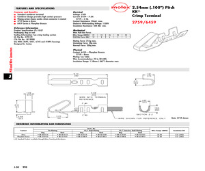
g Brass Phosphor Bronze Reel 08-50-0113 08-52-0101 15m" Gold Plating Bag 08-50-0114 08-52-0123 2.54mm (.100") Pitch KK(R) Cat Ear Terminal 5159 Reel 08-56-0109 08-65-0813 Bag 08-56-0110 08-65-0814 15m" Selective Gold Plating Reel 08-55-0101 08-65-0815 Bag 08-55-0102 08-65-0816 Features and Benefits Similar to 2759/6459 Series with cat ears Cat ears provide 2 high pressure points of contact Suitable for high vibrational requirements Wire Gauge (AWG) Insulation OD Lead-free 22-30 1.57 (.062) Yes Electrical Voltage: 250V Current: 3.0A Contact Resistance: 20 milliohms max. Dielectric Withstanding Voltage: 1000V AC Insulation Resistance: 1000 Megohms min. Reference Information Product Specification: PS-10-07 Packaging: Bag or reel Tooling Information: See crimp tooling section UL File No.: E29179 CSA File No.: LR19980 Use With: 2695, 5051 and 6471 Designed In: Inches Physical Contact: Phosphor Bronze and Brass Plating: Tin Wire Accommodation: 22 to 30 AWG Order No. Phosphor Bronze Bag 08-70-0049 Brass
 1 Pages, 83 KB, Original
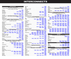
 numbers for the mating housing and crimp-style snap-in terminals are listed below. There may be equivalent connectors available from other manufacturers. J204 Molex P/N Connector Circuits (pins) 9 Mating Housing 22-01-3097 Crimp terminal (selective gold) 08-55-0102 Rated Contact Current 2.5 A Rated Wire Size AWG 22 thru 30 Table 4-4 J204 Mating Connectors 4.8 Signal Descriptions and Remarks Signal Description/Remarks AC Line Highest in potential compared to earth ground. Should be connected to the AC power switch. AC Neutral Closest in potential to earth ground. Should not be connected to a single-pole power switch. DC Return XL375 ground for all outputs and status/control signals. V1 The main output (+) V1 Sense (+) Remote sense for V1 at load (compensates for wiring losses) V1 Sense (-) Remote sense for DC Return at load (affects V1, see above) V1 Trim Adjusts V1 output voltage up to +/- 5% using an external resistor. See Section 3.5 V1 I-Share Current Share Signal common to all sharing XL375s
 30 Pages, 645 KB, Original
ing Tin Plating Bag * 08-50-0114 * 08-52-0123 Reel * 08-50-0113 * 08-52-0101 * US Standard Product, available through Molex franchised distributors J-30 990 Bag * 08-56-0110 * 08-65-0814 Reel * 08-56-0109 * 08-65-0813 15" Selective Gold Plating Bag Reel * 08-55-0102 * 08-55-0101 * 08-65-0816 * 08-65-0815 Wire Gauge (AWG) Insulation OD 22-30 22-30 1.57 (.062) 1.57 (.062)
 1 Pages, 53 KB, Original
p Tool 638118200 Insertion Tool 638120000 This document was generated on 11/30/2018 PLEASE CHECK WWW.MOLEX.COM FOR LATEST PART INFORMATION Mouser Electronics Authorized Distributor Click to View Pricing, Inventory, Delivery & Lifecycle Information: Molex: 08-55-0102
 2 Pages, 50 KB, Original
ow Receptacle AMP 2-635585-1 Header AMP 2-102973-5 Industry standard receptacle and header using 0.025 inch square posts with 100 mil pin spacing. I2C, P2 5 pin, Single Row Header, Molex 22-23-2051 Receptacle housing, Molex 22-01-3057; and Contacts, Molex 08-55-0102 Header and receptacle are keyed and include the locking ramp. Some Molex documentation defines pin 1s on opposite ends of the header and housing. BT656, J1 25 pin, D-Subminiature Sockets, AMP 745967-7 Pins, AMP 747912-2 Connectors and pinout defined by ITU-R BT.656 standard. CLK, J2 SMA Coaxial Jack, Johnson Components 142-0701-211 Plug, Johnson Components 142-0403-011 The clock interface is bidirectional. The connector must not be driven when the BT656 interface is active or when the Main connector clock pin is driven. Analog Outputs, J3-J6 BNC Coaxial Jack, Amphenol 31-5329 Plug, Amphenol 68175 Terminate each analog output with a 75 load from the center conductor to the cable shield for best results. Plated thru-holes in PCB Strande
 19 Pages, 275 KB, Original
ertificate of Compliance (PDF) Series image - Reference only General Product Family Series Application Crimp Quality Equipment Overview Packaging Alternative Product Name UPC Crimp Terminals 2759 Signal, Wire-to-Board Yes KK(R) Interconnect System - Molex 08-55-0102 (Loose) KK 254 800753749900 Physical Gender Material - Metal Material - Plating Mating Material - Plating Termination Net Weight Packaging Type Plating min - Mating Plating min - Termination Termination Interface: Style Wire Insulation Diameter Wire Size AWG Wire Size mm Female Brass Gold Nickel 0.064/g Reel 0.381m 0.762m Crimp or Compression 1.57mm max. 22, 24, 26, 28, 30 N/A Solder Process Data Lead-freeProcess Capability N/A Material Info Engineering Number 2759-(555)B Reference - Drawing Numbers Packaging Specification Product Specification Sales Drawing PK-2759-002-001 PS-10-07-001, TS-10-07-001 SD-2759 EU ELV Not Relevant EU RoHS China RoHS Compliant REACH SVHC Not Contained Per ED/61/2018 (27 June 2018) Halogen-Free Status Low-
 2 Pages, 47 KB, Original
ting connectors, if you want to make your own cables. Table B-1. Connector and Manufacture's Part Numbers Connector Pin Number/Pin Spacing/ Orientation Manufacturer Manufacturer's PN J2 - Ethernet 8-pin, 0.1", right angle Molex Housing = 10-11-2063 Pins = 08-55-0102 J3 - Serial 1 10-pin, 0.1", right angle Molex 10-89-1106 J4 - Floppy/ Parallel 26-pin, 0.1", right angle T&B Ansley or Spectra-Strip 609-2600M or 812-2622-134 J5 - Utility 10-pin, 0.1", right angle AMP or Molex 102387-1 or 22-55-3101 J6 - IDE 44-pin, 2mm, straight TEKA HM222BT1U-191-00 J7 - Power 10-pin, 0.1", right angle AMP or Molex Housing = 87456-5 or 22-55-2101 AMP or Molex Contact = 87523-6 or 16-02-0103 J8 - GPIO 10-pin, 2mm, straight Adam Tech or Samtec D2PH 2 10 SG .146/.118/.420 or TW-05-06-G-D-420-110 J9 - Serial 2 10-pin, 0.1", right angle Molex 10-89-1106 J10 - USB 5-pin, 0.1", right angle Molex 22-12-2054 J11 - Video 44-pin, 2mm, right angle Adam Tech or Astron 2PH2R44SGA AT-PH2-44-2-1-GF J13 - Serial 3 10-pin, 0.1", str
 72 Pages, 510 KB, Original


